In the world of precision machining, the blueprint is more than just a drawing—it’s a contract. But a simple callout like “±0.05mm” on a part can be ambiguous, leaving room for interpretation and potential failure. This is where Geometric Dimensioning and Tolerancing, or GD&T, becomes the universal language that ensures every part not only fits, but also functions as intended.
At Dongguan Huade Precision Manufacturing, our tight tolerance CNC machining services are built on a deep understanding of precision tolerance methods. We believe that a strong partnership begins with clear communication. This guide serves as a practical introduction to GD&T explained, helping you design with clarity and confidence so that we can deliver the perfect component, every time.
Beyond Basic Tolerances: Why GD&T is Essential
Traditional coordinate-based tolerancing has a major flaw: it can’t fully capture the true function of a part. It allows for a “square tolerance zone,” which often wastes valuable manufacturing space and can still lead to parts that technically meet the print but fail to assemble correctly.
Dimensional accuracy standards replaces this with a “functional tolerancing” approach. It specifies a part’s geometry and allows for a more flexible, cylindrical or spherical tolerance zone, which is more representative of a part’s actual functional requirements. The benefits are immense:
- Clarity and Unambiguity: precision tolerance methods removes guesswork from the manufacturing process.
- Reduced Cost: By specifying only the tolerances that are critical to function, you can often loosen non-critical tolerances, reducing machining time and cost.
- Improved Quality and Interchangeability: Geometric Dimensioning and Tolerancing ensures that parts from different batches will fit and function consistently, a cornerstone of mass production.
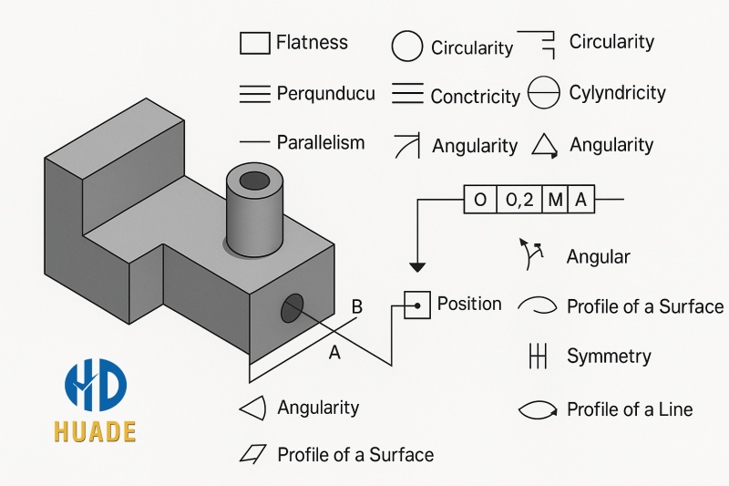
Decoding the Language: Common GD&T Symbols and Definitions
To master dimensional accuracy standards, you must understand its symbols. Here is a brief overview of the most commonly used symbols and what they mean for CNC machining:
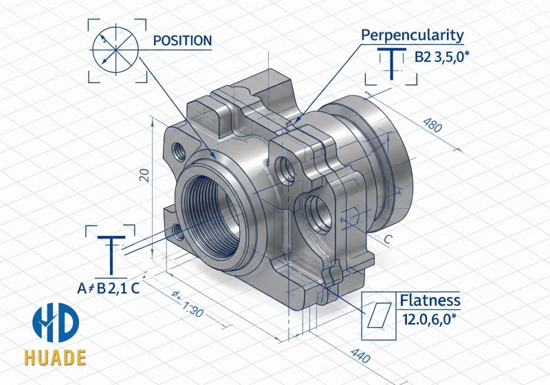
- Flatness (—): Ensures a surface is perfectly flat. This is crucial for components that must sit flush against another surface, such as seals or mounting plates.
- Perpendicularity (⊥): Specifies that a feature, like a hole or a surface, must be exactly 90 degrees to a datum plane. This is vital for aligning parts correctly.
- True Position (⊕): This is one of the most powerful precision tolerance methods symbols. It defines the ideal location of a hole or feature and allows for a cylindrical tolerance zone around that position, which is far more efficient and functional than a square one. Our CNC machines are programmed to achieve this with exceptional accuracy.
- Profile of a Surface (∩): Controls the entire shape of a complex, contoured surface. This is essential for aerospace parts, blades, or any non-uniform geometry.
- Concentricity (◎): Ensures that the center point of one feature is aligned with the center point of another, a key requirement for rotating parts.
How to Apply GD&T Effectively: A Practical Approach
Choosing the correct precision tolerance methods callouts is a delicate balance. Over-specifying can unnecessarily increase costs and manufacturing difficulty, while under-specifying can lead to part failure. Here is our advice for choosing the right tolerance:
- Identify Critical Functions: Begin by asking what the part’s most important functions are. Does it need to align with another part? Does it need a fluid-tight seal? This functional requirement will guide your dimensional accuracy standards choices.
- Establish a Datum Reference Frame (DRF): The DRF is the cornerstone of Geometric Dimensioning and Tolerancing. It provides a stable, repeatable reference point for all your dimensions and tolerances. A well-defined DRF is the first step to achieving predictable results.
- Prioritize Your Tolerances: Start by applying the tightest tolerances to the most critical features and then gradually loosen them for non-critical areas. This strategic use of tolerances is where you can achieve significant cost savings.
- Consider Tolerance Stack-up: In an assembly of multiple parts, the tolerances can add up. Our engineers perform tolerance stack-up analysis to ensure that all parts, even at their worst-case tolerance limits, will still assemble and function correctly.
Our Expertise in GD&T for CNC Machining
At Dongguan Huade Precision Manufacturing, our machinists and engineers are highly skilled in interpreting tolerance-based technical drawings. When you share your design files, you can trust us to capture your intent with precision and deliver parts that perform as expected.
We rely on standardized methods for defining size, form, and position tolerances to guide CNC programming, tool selection, and quality checks—ensuring that every component meets both dimensional accuracy and functional performance.
Whether you are a seasoned engineer or new to the world of Geometric Dimensioning and Tolerancing, we are here to support you. We can offer expert advice on how to optimize your designs for manufacturability and help you make informed decisions when choosing the right tolerance.
Ready to Ensure Your Designs are Perfectly Interpreted?
Don’t let a language barrier stand between your design and a perfect part. Partner with an expert for CNC machining who speaks your language.
Visit hdproto.com to see how our expertise in GD&T and precision manufacturing can bring clarity and quality to your next project.