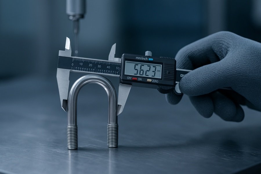
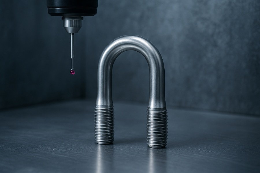
The foundation of robust industrial and automotive assemblies rests not just on the raw strength of its components, but on their dimensional accuracy. While an engineer might start with a U bolt sizes chart for standard specifications, the real challenge in modern heavy-duty applications lies in manufacturing these and other critical components, like U-joint needle bearings, with tolerances that often dip into the sub-micron range.
This requires a sophisticated approach that moves past simple chart lookup and dives deep into advanced machining technologies, material science, and rigorous quality control.

The Illusion of “Standard”: Why Charts Are Just the Start
For many procurement specialists, a U bolt sizes chart represents a final decision. They select a diameter, a thread pitch, and a leg width, and the job seems done. However, for applications facing high fatigue, extreme loads, or corrosive environments—such as marine risers or heavy mining truck suspensions—a standard part simply won’t suffice.
The dimensions listed in any generic u bolt sizes chart are nominal. The performance of the final assembly is determined by the manufacturing variance around those nominal numbers. This variance is defined by tolerance—the acceptable deviation from the perfect size.
When discussing fasteners like what size head is a 3/8 bolt or what size head on 1/2 bolt, the focus shifts from the overall shape to the critical interfaces:
- Thread Pitch and Diameter: Poor thread profile or diameter variation leads to uneven load distribution, resulting in premature fastener failure. Precision CNC turned bolt manufacturing is essential here to maintain the Class 3 thread fit required by many industrial standards.
- Head and Flange Dimensions: The contact area, defined by the head size, dictates clamping force integrity. Precise control over the head-to-shank fillet radius and bearing surface flatness prevents stress risers.
Manufacturing these components often requires highly specialized custom U-bolt machining services that can handle materials like high-strength alloy steels or exotic metals while holding extremely tight fastener tolerance standards.
📏 Standard U Bolt Sizes Chart for Industrial and Automotive Applications
| Nominal Diameter (in.) | Thread Pitch (TPI) | Inside Width (in.) | Inside Length (in.) | Radius (in.) | Recommended Torque (ft·lb) |
|---|---|---|---|---|---|
| 1/4″ | 20 | 1-1/8″ | 2″ | 9/16″ | 6 |
| 5/16″ | 18 | 1-3/8″ | 2-1/2″ | 11/16″ | 11 |
| 3/8″ | 16 | 1-5/8″ | 3″ | 13/16″ | 20 |
| 7/16″ | 14 | 1-7/8″ | 3-1/2″ | 15/16″ | 32 |
| 1/2″ | 13 | 2-1/8″ | 4″ | 1-1/16″ | 48 |
| 9/16″ | 12 | 2-3/8″ | 4-1/2″ | 1-3/16″ | 70 |
| 5/8″ | 11 | 2-5/8″ | 5″ | 1-5/16″ | 95 |
| 3/4″ | 10 | 3″ | 6″ | 1-1/2″ | 170 |
| 7/8″ | 9 | 3-3/8″ | 7″ | 1-11/16″ | 270 |
| 1″ | 8 | 3-3/4″ | 8″ | 1-7/8″ | 400 |
How to Read the Chart:
– Nominal Diameter = Bolt thread size.
– Thread Pitch (TPI) = Number of threads per inch.
– Inside Width & Length = Dimensions between the bolt legs and along the legs.
– Radius = The curvature of the U-bend.
– Recommended Torque = Tightening torque to achieve proper clamping without overstressing the bolt.
For detailed specifications, visit ASME B18.31.5 U-Bolt Standard.

The Sub-Micron World of Motion: U-Joint Needle Bearings
If fasteners are the anchors of an assembly, then U-joint needle bearings are the critical articulators, enabling smooth power transmission under angular deflection. These small yet mighty components operate under immense pressure and constant cyclical loading, making manufacturing precision a life-or-death matter for the machinery they serve.
Key Manufacturing Challenges
- Material Hardness & Surface Finish: Needle rollers must be made from through-hardened steel with mirror-like finishes to prevent fatigue cracks.
- Dimensional Uniformity: Variations as small as 2–3 microns can cause uneven load distribution, leading to early bearing failure.
- Component Geometry: Bearing cups, crosses, and yokes must remain perfectly concentric and aligned.
Advanced Machining: Bridging the Gap between Design and Performance
To consistently achieve sub-micron accuracy, modern manufacturing employs:
- Temperature and Environment Control — Maintaining room stability to prevent metal expansion.
- Dynamic Tool Compensation — Real-time CNC adjustments during machining.
- Integrated Measurement and Validation — Using CMMs, laser micrometers, and vision systems for precise inspection.
The Value Proposition of True Precision
Precision is not an aspiration—it’s measurable, repeatable, and guaranteed. By partnering with a facility focused on precision machining for needle bearings and custom U-bolt machining, companies benefit from:
- ✅ Extended Component Life
- ✅ Reduced Assembly Issues
- ✅ Guaranteed Reliability
Moving beyond the simple u bolt sizes chart and embracing advanced precision engineering is the hallmark of a truly reliable supplier. Contact us to get more information!
