Let’s be honest—when a humanoid robot jitters in a static pose, most teams blame software first.
But in CNC machining for humanoid robots, tiny datum and fit errors can create friction ripple and micro-backlash that no controller can fully hide.
You’ve tuned the torque loop, refined the PID gains, and validated your motion in simulation. Then your humanoid robot holds a static pose—and the arm starts shaking. The first instinct is always software: encoder noise, drive backlash, controller bandwidth, filtering.
But in real humanoid systems, joint jitter is often the control loop fighting hardware errors that are “small on paper” and massive in kinematics.

CNC manufacturing expert with 15+ years of experience. William helps engineering teams turn prototypes into stable production parts through DFM optimization, tolerance planning, machining strategy selection, and inspection-driven quality control.
william@hdproto.comFor any CNC-machined part — whether shafts, housings, brackets, manifolds, or structural components — the foundation of reliable manufacturing starts with clean geometry, well-defined datums, and machining-friendly features that minimize re-clamping risks.
We support function-driven tolerances (down to ±0.01 mm when required) and offer full inspection options including CMM reports, thread gauges, and surface-finish verification to ensure repeatability from prototype to production.
CONTACT OUR EXPERT NOWAt Dongguan Huade Precision Manufacturing Co., Ltd., we support robotics teams with CNC machining for humanoid robot parts—especially actuator housings, bearing seats, output links, and precision interfaces that decide whether a joint feels “alive” or “nervous.”
Quick Technical Summary (for engineers & search engines)
This article focuses on the mechanical root causes of joint jitter in humanoid robot joints and how precision CNC machining reduces them, including: GD&T datum strategy, bearing bore concentricity/runout, single-setup 5-axis machining, CMM inspection, thermal expansion effects on interference fits, and thin-wall high-speed machining for weight reduction.
The Real Problem: “Hardware Ghosts” That Look Fine on Drawings
A typical joint stack is not one feature—it’s a chain:
Bearing seat → Actuator shaft interface → Harmonic drive / gearbox mount → Output link
When one interface is slightly off-axis or out-of-flat, the joint can still “assemble,” but it won’t run smoothly. The controller then compensates in real time, and what you observe as jitter is often mechanical binding, micro-backlash, or temperature-driven fit drift.
Below are three “hardware ghosts” we see repeatedly in humanoid robot machining projects—and how we remove them.
Ghost #1: Stack-Up Errors (Where GD&T Meets Kinematics)
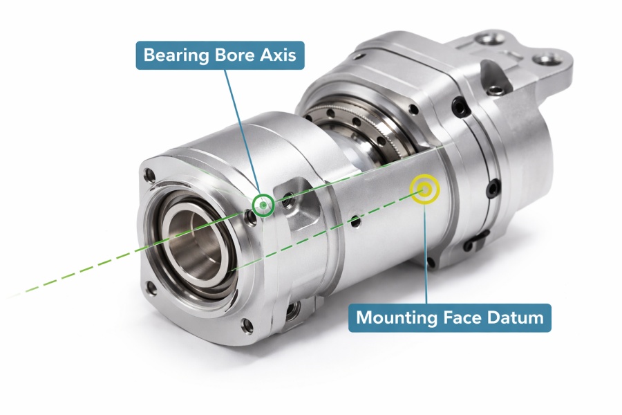
Most shops treat a hole as an isolated feature: “Ø20 H7, pin fits, done.” In a high-DoF humanoid limb, that same bore is a datum-critical element in a precision kinematic chain.
What goes wrong
Even a small misrelationship between a bearing bore axis and a mounting face can create:
- eccentric friction during rotation
- periodic torque ripple
- non-linear stiction (stick-slip) that triggers control oscillations
You may see the joint behave “fine” in one region and jitter in another because the error is geometric, not algorithmic.
Common symptoms engineers notice
- Current spikes that don’t match simulation (extra torque needed to overcome binding)
- Low-frequency oscillation under load (control loop fighting mechanical friction variation)
- Short bearing life (abnormal loading from misalignment)
How we machine it at Huade
We don’t machine “holes.” We machine datum systems.
Single-setup machining for critical datums
For parts like actuator housings, we prefer machining the bearing bores, mounting faces, seal grooves, and alignment features in a single 5-axis setup whenever possible. Fewer reclamps means fewer compounded errors.
CMM verification tied to your GD&T
We inspect the geometry against the drawing intent—especially the relationships that matter in robot joints (axis-to-face, face-to-face, bore-to-bore). If your drawing references ASME Y14.5 GD&T, we align inspection strategy to that intent.
Practical takeaway: If a joint jitters at steady pose, verify bore axis alignment, perpendicularity/flatness of mounting faces, and runout/concentricity before rewriting code.
Ghost #2: Thermal Expansion Drift (Interference Fits That Don’t Stay Interference)
Humanoid joints are thermally dense. Motors and drives generate heat fast, and sealed housings can climb in temperature during continuous motion.
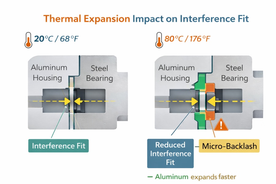
What goes wrong
A press-fit that feels perfect at room temperature can change once the joint heats up. Aluminum and steel expand at different rates, and that can turn a tight fit into micro-backlash—or shift preload enough to change friction behavior.
What it looks like in testing
- The robot feels “stable” when cold
- Jitter appears after warm-up or during repeated cycles
- Performance varies across sessions even with identical control settings
How we reduce thermal-fit risk
DFM review that asks the physics questions
Instead of blindly following a PDF tolerance, we ask:
- What is the estimated joint temperature range?
- Is the bearing seat in a heat-soaked cavity or near a motor stator?
- Is the fit meant to hold preload, prevent creep, or control micro-motion?
Fit strategy options (depending on your architecture)
Depending on your assembly and service strategy, we can support:
- tighter control of bore size and roundness to stabilize press-fit behavior
- surface finish strategies to reduce micro-slip
- design adjustments (where appropriate) to make the fit stable across temperature
Passive thermal help without weight penalty
For some actuator housings, teams choose to add integrated external micro-fin features to increase surface area for passive cooling—no extra brackets, no extra assembly weight—just smarter geometry.
Practical takeaway: If jitter appears “after warm-up,” treat it like a thermal-mechanical problem first, not a controller problem.
CNC manufacturing expert with 15+ years of experience. William helps engineering teams turn prototypes into stable production parts through DFM optimization, tolerance planning, machining strategy selection, and inspection-driven quality control.
william@hdproto.comFor any CNC-machined part — whether shafts, housings, brackets, manifolds, or structural components — the foundation of reliable manufacturing starts with clean geometry, well-defined datums, and machining-friendly features that minimize re-clamping risks.
We support function-driven tolerances (down to ±0.01 mm when required) and offer full inspection options including CMM reports, thread gauges, and surface-finish verification to ensure repeatability from prototype to production.
CONTACT OUR EXPERT NOWGhost #3: Heavy Shell Syndrome (Inertia Is the Enemy of Humanoid Motion)
In humanoids, grams multiply. Extra mass at the wrist demands more torque at the elbow, which demands more at the shoulder, which raises power and thermal load across the whole arm.
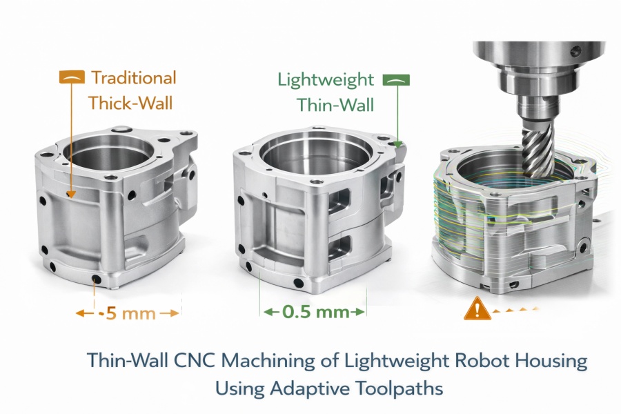
Many suppliers push conservative wall thickness because thin walls chatter, warp, and are hard to fixture. That protects their process, not your robot.
What goes wrong
- Walls get “beefed up” for manufacturability
- inertia rises
- response slows, power rises, thermal drift worsens
- the robot “feels” less controllable even with good control code
How we machine thin-wall parts reliably
High-speed machining + workholding that matches the geometry
We use process choices that make thin walls feasible, including:
- custom soft jaws / dedicated fixtures
- adaptive toolpaths to reduce cutting force spikes
- stress-aware sequencing (remove material in a way that avoids warpage)
What thin-wall is realistic
We regularly produce lightweight housings and structural robot components where thin sections are required. In some designs and alloys, thin walls can be achieved down to ~0.5 mm, but final capability depends on geometry, rib strategy, and functional load cases.
Practical takeaway: In humanoids, “machinability-driven weight” often becomes a hidden tax on stability and control.
What to Send for a Fast, Useful DFM Review (So We Don’t Guess)
To help us identify jitter-risk interfaces quickly, send:
- STEP/Parasolid of the part (and mating stack if available)
- drawing with GD&T (or the intent: what must be coaxial, what must be flat)
- bearing/drive model info (seat type, preload intent, assembly method)
- target temperature range (even a rough estimate helps)
- critical surfaces: where you measure runout, backlash, and torque ripple
Inspection & Deliverables We Can Provide (Typical Robotics Requests)
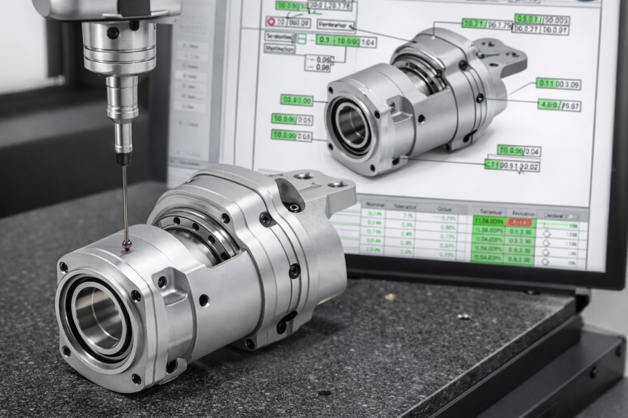
Depending on your stage (prototype vs pilot), teams commonly request:
- CMM report for datum relationships and key bores/faces
- first-article inspection priorities aligned to joint interfaces
- surface finish documentation for friction-critical surfaces
- process notes for repeatability in small batches
Stop Debugging Physics with Code
You can’t PID your way out of a misaligned bearing seat. You can’t filter away drift caused by unstable fits across temperature. Great humanoid motion starts with geometry that respects kinematics and physics.
At Dongguan Huade Precision Manufacturing Co., Ltd., we support robotics teams as more than make-to-print. We focus on the interfaces that decide whether your joint is smooth, quiet, and repeatable—so your software tuning stays meaningful.
Want a technical DFM review?
Send your STEP files and key requirements. Our engineers will review your joint-critical interfaces and share practical machining/inspection feedback.
FAQ
FAQ 1: What mechanical issues most commonly cause joint jitter in humanoid robots?
The most common are datum misalignment in bearing seats, bore-to-face relationship errors, micro-backlash from unstable fits, and friction nonlinearity caused by geometric stack-up.
FAQ 2: Concentricity vs runout—what should I specify for bearing bores?
If your priority is rotational behavior at the assembled interface, runout-related controls are often more directly tied to performance. For complex stacks, use a datum strategy that reflects the real assembly and measurement method.
FAQ 3: Why does jitter appear only after the robot warms up?
Temperature changes can alter interference fits, preload, and friction behavior. Even small thermal drift can introduce micro-motion or change torque ripple, which the controller amplifies under high gain.
FAQ 4: How can CNC machining reduce harmonic drive or gearbox-related oscillation?
Precision machining can reduce oscillation by stabilizing alignment between bearing seats, gearbox mounts, and output interfaces—reducing eccentric friction, binding, and torque ripple that excite the control loop.
FAQ 5: Can thin-wall designs really be machined without warpage?
Yes, with the right workholding, toolpaths, and stress-aware sequencing. Thin-wall feasibility depends on geometry, alloy, rib strategy, and the functional stiffness required.
FAQ 6: What should I send to get a useful DFM review for humanoid robot parts?
Send STEP + drawing (or mating intent), bearing/drive details, assembly method, operating temperature range, and highlight your joint-critical datums and surfaces for runout/backlash control.