Machining blueprint symbols—also called CNC blueprint symbols, blueprint machining symbols, or machine blueprint symbols—form the core language of engineering drawings. Whether you are reviewing a spec drawing, preparing a CNC project, or communicating manufacturing requirements to a supplier, these standardized symbols ensure accuracy, consistency, and clear engineering intent.
At Dongguan Huade Precision Manufacturing Co., Ltd. , our engineering team reviews thousands of blueprints each month. A correct interpretation of machining blueprint symbols ensures consistent ±0.01 mm precision, fast quoting, reduced errors, and reliable prototype-to-production workflows.
This comprehensive guide combines essential blueprint symbols, GD&T features, surface finish marks, and blueprint reading essentials into one complete reference.
🧭 1. What Are Machining Blueprint Symbols?
Machining blueprint symbols — standardized icons used across CNC engineering drawings — define key manufacturing requirements such as:
- Dimensions
- Tolerances
- Hole features
- GD&T controls
- Surface finishes
- Depth and radius details
- Manufacturing instructions
Machining blueprint symbols create a universal manufacturing language that ensures machinists, engineers, QC inspectors, and suppliers interpret drawings accurately and consistently — reducing errors and improving production efficiency worldwide.
🎯 2. Why Machining Blueprint Symbols Matter in CNC Manufacturing
Correct interpretation influences:
✔ Machining strategy
(tool paths, cutter selection, tolerances to hold)
✔ Inspection method
(CMM, micrometers, gauges)
✔ Blueprint-to-part accuracy
(reduces rework and ensures functional assembly)
✔ Manufacturing cost and quoting
(tight tolerances and surface finish raise cost)
✔ Communication efficiency
(eliminates misunderstandings between engineers and machinists)
At Dongguan Huade Precision Manufacturing Co., Ltd., every drawing undergoes complete DFM review, tolerance check, and GD&T feasibility verification before machining begins.
📘 3. Common CNC Blueprint Symbols and Their Meanings
This section covers the most common CNC blueprint symbol topics engineers frequently search for, including:
- machining blueprint symbols
- blueprint symbols for machining
- blueprint machining symbols
- cnc blueprint symbols chart
- machining blueprint symbols list
- machining blueprint symbols pdf
Below is your complete reference list of blueprint symbols and their meanings.
3.1 Dimensional Symbols (Found on Most Spec Drawings)
| Symbol | Meaning |
|---|---|
| Ø | Diameter (common on turning & drilling drawings) |
| R | Radius |
| ↧ | Depth |
| ± | Bilateral tolerance |
| +0/-0.02 | Unilateral tolerance |
| ↔ | Linear dimension direction |
| ↕ | Vertical dimension |
3.2 Hole & Feature Symbols
| Symbol | Meaning |
|---|---|
| ⌴ | Counterbore (CB) |
| ⌵ | Countersink (CSK) |
| ⌓ | Spotface |
| M6 × 1 | Metric thread |
| ¼-20 UNC | Imperial thread |
These appear in all blueprint symbols for machining and are essential for CNC drilling and milling.
3.3 Surface Finish Symbols (Ra)
| Symbol | Meaning |
|---|---|
| Ra 3.2 μm | Standard machining finish |
| Ra 1.6 μm | Fine finish |
| Ra 0.8 μm | Precision sealing surface |
| Ra 0.4 μm | Mirror/optical finish |
| / | No machining required |
| /\ | Surface must be machined |
Surface finish symbols are critical in machining blueprint symbols charts.
3.4 Complete GD&T Symbols
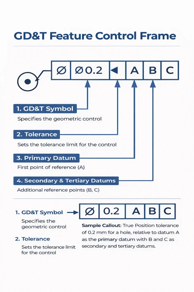
Example of a GD&T feature control frame used in CNC machining blueprints.
These appear on almost all spec drawings requiring precision.
| Symbol | Meaning |
|---|---|
| ⌖ | True Position |
| ∥ | Parallelism |
| ⟂ | Perpendicularity |
| ○ | Circularity |
| ⌭ | Cylindricity |
| ⌯ | Runout |
| ⌰ | Total Runout |
| ∡ | Angularity |
| ⌒ | Profile of a Line |
| ⌓ | Profile of a Surface |
| □ | Datum Feature |
| ⫽ | Flatness |
| ≡ | Feature Control Frame |
Related topics engineers often search for include:
✔ blueprint machining symbols
✔ complete GD&T symbols
✔ machining blueprint symbols chart
📝 4. Blueprint Reading Essentials (Blueprint Reading Symbols Machining)
When reading a CNC blueprint, always locate:
✔ 1. Title Block
Material, finish, tolerances, revision level.
✔ 2. Datum Scheme
Defines which surfaces control measurements.
✔ 3. GD&T controls
Critical for fit, alignment, and assembly.
✔ 4. Hole & thread notes
Often include hidden requirements like chamfers or deburring.
✔ 5. Section, detail, & auxiliary views
Provide clarity on complex features.
✔ 6. General Tolerances
Often found in the drawing notes.
Understanding these blueprint reading symbols helps engineers and buyers avoid costly misunderstandings.
📐 5. What a CNC-Ready Spec Drawing Must Include
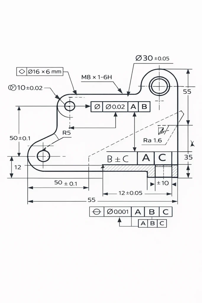
Sample machining blueprint with GD&T, tolerances, datums, and standard machining symbols.
A complete, manufacturer-ready spec drawing contains:
- 2D PDF drawing
- 3D STEP model
- All dimensions clearly defined
- Tolerances and GD&T
- Surface finish marks
- Hole/thread tables
- Material & hardness
- Notes on chamfers, deburring, sharp edges
- Heat treatment, coating, or surface finish instructions
This dramatically reduces quoting time and prevents mistakes.
🚀 6. From Blueprint to Machining: How Dongguan Huade Ensures Accuracy
We use blueprint symbols throughout our process:
✔ DFM Review
Confirm tolerance feasibility and tool access.
✔ Machining Plan
Tool paths, fixturing, and process sequence.
✔ In-Process QC
Measurement at key stages.
✔ Final Inspection
CMM, pin gauges, micrometers.
✔ Optional Full Inspection Report
For aerospace, medical, and high-precision industries.
Our 3-axis, 4-axis, and 5-axis machining centers deliver ±0.01 mm accuracy with 2–3 day rapid prototyping.
📥 7. FREE Download — Machining Blueprint Symbols PDF
We created a printable machining blueprint symbols PDF that includes:
✔ Full symbol list
✔ Surface finish chart
✔ GD&T reference table
✔ Blueprint reading guide
Download PDF Guide (Free)
📥Machining Blueprint Symbols PDF Guide
This downloadable guide also helps engineers searching for topics like:
- machining blueprint symbols PDF
- CNC blueprint symbols PDF
- blueprint symbols machining chart
🏁 Conclusion
CNC blueprint symbols are the universal language of manufacturing. Understanding dimensional symbols, GD&T features, surface finish marks, and blueprint reading rules ensures:
- Accurate communication
- Lower machining cost
- Faster quoting
- Fewer production errors
- Better engineering-to-manufacturing alignment
At Dongguan Huade Precision Manufacturing Co., Ltd., we help global customers interpret drawings, optimize designs, and manufacture high-precision CNC parts with world-class consistency.
Have a blueprint, STEP file, or technical drawing? Our engineering team can review it and provide a fast, accurate quotation.
Simply fill out the form below and we will get back to you shortly.