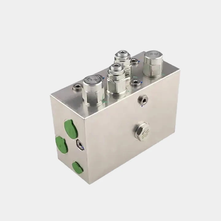
Hydraulic Valve Manifold Block Machining
A hydraulic valve manifold block is a functional interface—not just a drilled block.
Ports, threads, cross-drilled passages, and sealing faces must stay consistent over long runs.
Production Machining Playbook
This is a production playbook: material behavior → CAM programming → tool selection → burr control → process stability → cost optimization.
The goal is simple: parts that run stable, efficient, and “good to use” in real assemblies.
For general concepts and inspection basics, see our manifold block machining guide.
For a step-by-step DFM checklist (threads, sealing faces, deburring, and inspection), read our hydraulic manifold block checklist.
Need a quote? Contact us and share your material, quantity, and port/thread requirements.
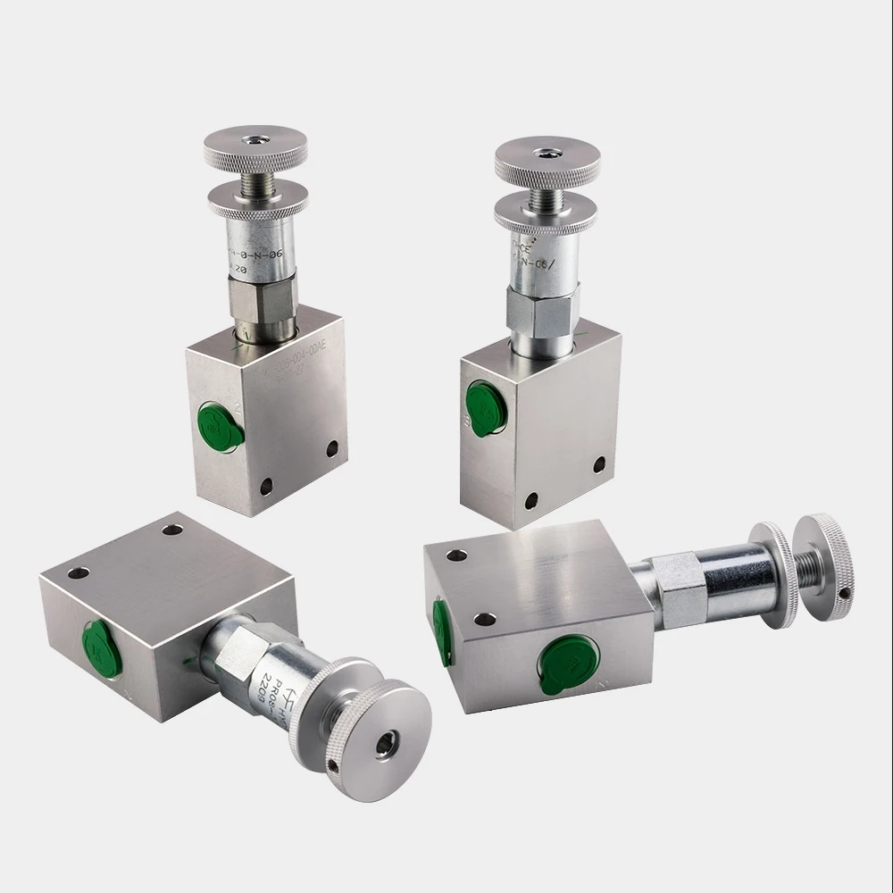
1) What Makes Valve Manifold Blocks Hard in Production
Valve blocks concentrate many risk features into a compact part.
When production volume rises, small variations turn into expensive problems.
Typical cost and quality drivers include:
- Many ports and threads (assembly consistency depends on them)
- Cross-drilled intersections (burrs and trapped chips)
- Seal-critical faces and grooves (leak paths)
- Long drilling depth in some channels (tool wear and drift)
- Cleaning requirements (becomes a bottleneck if not designed)
If you want predictable cost, design your process to prevent variation, not chase it later.
2) Material Behavior First (Stainless, Aluminum, and Beyond)
Hydraulic valve manifold blocks can be aluminum or steel/stainless depending on pressure, corrosion, and environment.
Different materials require different tool and program behavior.
Practical material map
| Material family | Why it’s used | Production risk | What to control first |
|---|---|---|---|
| Aluminum (6061/7075) | lightweight, fast cycle | burrs, thread damage | chamfers, burr plan, handling protection |
| Carbon steel | strength, wear | tool wear, heat | tool life rules, stable cutting |
| Stainless (304/316/17-4) | corrosion resistance | burrs, tool wear, heat | tool life, intersection burr strategy |
| Engineering plastics | corrosion/weight | deformation, thread pullout | workholding, conservative threading |
The best practice is not “one recipe.”
It’s choosing a recipe that keeps tool life and burr behavior predictable.
3) CAM Programming Strategy That Scales
“Fast” is only useful if it stays stable for months.
A scalable CAM plan protects datums, controls burr formation, and avoids unnecessary re-clamping.
A scalable operation route (example)
Op10 — Datum & squaring
Create reference faces early.
Datums are the foundation of repeatability.
Op20 — Primary drilling and major ports
Drill the main network with controlled heat and chip evacuation.
Leave finishing allowance where needed.
Op30 — Cross-drilling (planned intersections)
Sequence cross holes to reduce burr size.
Keep access for internal deburring and cleaning.
Op40 — Threading & entry chamfers
Thread after geometry is stable.
Standardize entry chamfers to protect assembly and sealing.
Op50 — Finish seal-critical faces
Finish sealing interfaces in controlled passes.
Avoid random toolpaths that create leak paths.
Op60 — Deburr, clean, protect
Treat cleanliness as part of the route.
Packaging protection matters as much as machining.
Two CAM rules that reduce cost
- Stop creating new burrs late in the route.
Finish intersections and deburring strategy before cosmetic work. - Keep thermal behavior predictable.
Heat changes tool life, burr formation, and surface condition.
4) Tooling Strategy (What Actually Works)
Tooling stability is the fastest path to cost control.
Unplanned tool wear becomes drift, rework, and scrap.
4.1 Drilling & cross-drilling: control intersections
Intersections are where burrs are born.
In valve blocks, burr fragments become contamination and unstable behavior.
Production-safe approach:
- Drill sequencing designed around intersection burr size
- Rigid holders + consistent coolant strategy
- A defined internal deburring method (not external-only)
- Sampling checks early in runs to validate burr behavior
4.2 Threading: tap vs thread mill (choose by risk)
Both methods can work. The decision is about consistency, recoverability, and cost.
| Method | Best when | Main risk | Production note |
|---|---|---|---|
| Tapping | stable setup, low risk threads | breakage, chip issues | enforce tool-life rule |
| Thread milling | critical ports, long runs | longer cycle | stable + recoverable |
A hybrid approach is often most efficient:
tap non-critical ports, thread-mill the ports that must be perfectly repeatable.
4.3 Finishing seal faces: keep it controlled
Seal faces and grooves are functional surfaces.
Your finishing plan should avoid surface patterns that encourage leak paths.
Key habits:
- One consistent finishing method for seal-critical faces
- Controlled edge break near grooves/ports
- Handling protection between ops (avoid scratches)
5) Burr Control & Cleanliness Without Killing Efficiency
If burr control depends on “manual extra work,” cost becomes unpredictable.
The goal is a repeatable burr strategy that does not slow the line.
A repeatable burr plan
- Reduce burr creation via drill order and breakthrough control
- Use deburring methods that reach internal intersections
- Validate with sampling checks when starting a run
- Keep cleaning aligned to chip behavior of the material
Cleanliness as a process gate
For valve blocks, internal cleanliness directly affects stability.
A part can measure right and still fail if chips remain inside.
Practical controls:
- Defined cleaning + drying process
- Port plugs/caps after cleaning
- Controlled packing so parts don’t get re-contaminated
6) A Real Long-Run Example: 24/7 Production for Over Two Years
Short prototype runs rarely reveal what drives cost.
Long production runs do.
For one long-term customer, we’ve produced this type of hydraulic valve manifold block in continuous operation—24-hour CNC machining with scheduled stops for tool changes and routine checks—for more than two years.
What went wrong early (and how we fixed it)
Problem:
After several hours of running, thread/port quality gradually drifted.
Parts still looked fine, but assembly torque and port-entry condition became less consistent.
In addition, some deep holes could not be kept upright during packaging, which increased the risk of edge contact and handling-related variation.
Root cause:
CAM/programming parameters were not optimized accurately enough, and tool wear plus thermal drift changed breakthrough behavior and edge quality at port entries.
That drift increased edge-cleanup (deburring) time and led to occasional rework.
Fix (process, not luck):
- We applied rule-based tool life and scheduled replacement
- We stabilized cutting conditions in CAM to reduce heat peaks
- We added an in-process check on a control feature (port entry/chamfer + thread gauge sampling)
Outcome:
Assembly became more consistent, burr-related rework dropped, and cycle time stayed predictable shift after shift.
That stability is where cost optimization becomes real.
7) Cost Optimization Without Losing Reliability
Cost reduction should come from removing variation.
Not from skipping critical steps.
High-impact levers:
- Tool life rules (planned replacement prevents late-run drift)
- Stable CAM parameters (reduces heat and hardening)
- Intersection burr prevention (reduces manual labor and scrap)
- Focused inspection (verify what controls sealing and stability)
- Cleanliness discipline (protects valve behavior and reduces returns)
8) Inspection Flow That Fits Production
Inspection should match risk.
Not every feature deserves the same effort.
Recommended verification checklist
Threads & ports
- Thread gauges for specified ports
- Entry chamfer condition (no burrs, no damage)
Seal-critical faces/grooves
- Surface condition review
- Edge condition (no sharp burrs, no nicks)
Critical relationships (when needed)
- Datum-to-port position checks
- Face-to-feature relationships for stack-sensitive assemblies
- CMM only where relationships truly matter
Cleanliness
- Validate cleaning route
- Check packaging protection
Quick alignment table
| Feature | Failure risk | Verify with |
|---|---|---|
| Cross-drill intersections | burrs, debris | deburr plan + sampling checks |
| Threads | leaks, assembly variability | thread gauges + chamfer review |
| Seal faces/grooves | internal leakage | surface/edge condition + flatness if required |
| Cleanliness | instability | cleaning process + protection |
FAQ (Quick Answers)
1: Why do valve blocks feel “unstable” even when dimensions look fine?
Because stability depends on burr fragments, edge condition, and cleanliness—not size alone. Cross-drilled intersections are a common hidden source.
2: What is the most common cost driver in long-run valve block production?
Process drift: tool wear and thermal variation that increase deburring time, thread variability, and rework.
3: Tap or thread mill—what’s better?
Both can be right. Use tapping for low-risk ports with stable chip control, and thread milling for critical ports where repeatability and recovery matter.
4: Do I need CMM for every batch?
Not always. Use CMM when critical relationships drive assembly outcomes. Otherwise, inspect by risk and validate the process early.
5: What should I tell a supplier to get consistent quality?
Ask for a defined tool-life rule, an internal deburring plan for intersections, a cleaning/packing control plan, and verification methods that match your critical interfaces.
Get a Fast Quote
Request a quote / DFM review
In the message box, please include material/grade, quantity, pressure range, port/thread standard (NPT/BSPP/ORB), sealing method, and any critical faces/threads.
If you have a STEP file or drawing, mention it and we’ll follow up.