Metal grooving often looks like a simple feature—just a narrow channel on a drawing. In real manufacturing, metal grooving is where parts start to leak, vibrate, seize, or fail assembly if groove width, depth, corner radius, burr condition, and surface finish are not controlled as one system. That is why grooving in machining is treated as a functional feature in aerospace, robotics, hydraulics, medical devices, and other high-reliability industries.
At Dongguan Huade Precision Manufacturing Co., Ltd (HDProto), we produce groove features on CNC lathes and CNC milling centers for shafts, housings, valve bodies, manifolds, brackets, and assemblies. When a groove must seal (O-ring groove), lock (retaining ring / snap ring groove), or relieve interference (undercut / relief groove), we approach it the same way we approach critical fits: stable workholding, predictable chip control, and inspection aligned with real function—especially at the edge condition where most failures begin.
Capability note (typical): on suitable parts with stable datums and process control, our turning tolerance can reach 0.005 mm, and our milling tolerance can reach 0.01 mm, depending on geometry, material, and measurement plan.
1) Groove-first thinking: define what the groove must do
Before choosing an insert or a toolpath, define the groove’s job. A groove typically falls into one of these categories:
Seal grooves (O-ring groove / gasket groove / face seal groove).
Priority is consistent width–depth geometry, stable surface finish in the sealing zone, and burr-free edges.
Retention grooves (retaining ring groove / snap ring groove).
Priority is groove width accuracy, controlled edge condition (sharp vs specified break), and repeatability across batches.
Relief grooves (thread relief / undercut / clearance groove).
Priority is eliminating interference, supporting assembly clearance, and controlling stress risers.
Fluid / lubrication grooves (channels, oil grooves, vent grooves).
Priority is consistent depth and cleanliness to avoid contamination, flow restriction, or particle trapping.
This is why “metal grooving” is not one operation—it is a family of decisions tied to function and failure risk.

CNC manufacturing expert with 15+ years of experience. William helps engineering teams turn prototypes into stable production parts through DFM optimization, tolerance planning, machining strategy selection, and inspection-driven quality control.
william@hdproto.comFor any CNC-machined part — whether shafts, housings, brackets, manifolds, or structural components — the foundation of reliable manufacturing starts with clean geometry, well-defined datums, and machining-friendly features that minimize re-clamping risks.
We support function-driven tolerances (down to ±0.01 mm when required) and offer full inspection options including CMM reports, thread gauges, and surface-finish verification to ensure repeatability from prototype to production.
CONTACT OUR EXPERT NOW2) Where CNC grooving happens: lathe vs mill
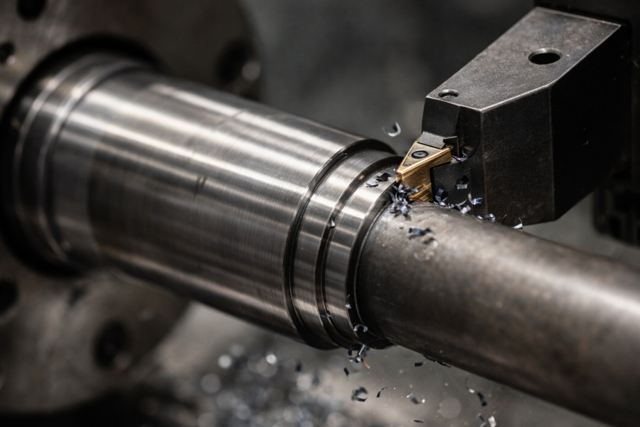
Many people treat CNC grooving as a lathe-only topic. In practice, groove machining happens on both turning and milling setups.
CNC lathe grooving is ideal for concentric features on round parts: OD grooves, ID grooves, and face grooves. It is fast, repeatable, and naturally aligned to rotational datums.
CNC milling grooving is common for slots, channels, and non-axisymmetric grooves on plates, housings, frames, and complex 3D parts.
Even when the same groove dimension is achievable by either method, the risk profile changes. Turning grooves often struggle with chip packing and tool deflection in narrow cuts, while milling grooves often struggle with chatter, burr control, and corner accuracy depending on cutter engagement and toolpath strategy.
3) The groove failure map: six problems that create scrap and assembly pain
Most groove failures repeat the same patterns. If you control these six, your groove yield and assembly reliability rise sharply:
- Chip packing inside the groove → scratched walls, broken edges, tool breakage, poor finish
- Tool overhang too long → chatter, tapered grooves, inconsistent depth
- Insert geometry not matched to material → built-up edge (Al), rapid wear (SS), broken corners
- Feed strategy not matched to groove width/depth → rubbing instead of cutting, unstable finish
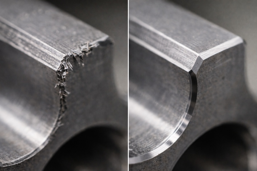
- Burrs at groove edges → seals cut during assembly, rings won’t seat, hidden contamination
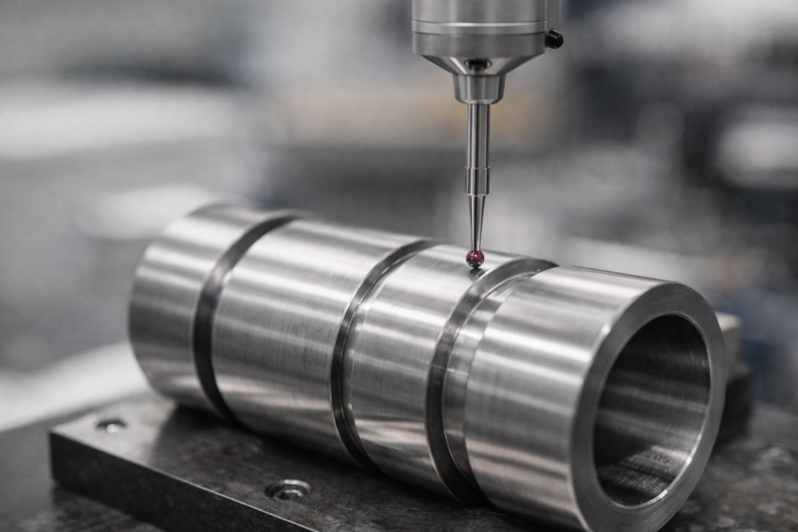
- Inspection mismatch → parts “pass” dimensionally but fail functionally in assembly
Good metal grooving is not about one “perfect parameter.” It is about repeatable control of these six variables across real production conditions.
4) Material × Application (Light Engineering Table)
| Material | Typical metal grooving applications | What to watch in CNC grooving | HDProto approach |
|---|---|---|---|
| 6061 Aluminum | channels, housings, light retention grooves | built-up edge, burrs, long stringy chips | sharp inserts, stable coolant, standard deburr |
| 7075 Aluminum | structural grooves in load paths | edge chipping, finish sensitivity | conservative entry, rigid workholding |
| Stainless 304/316 | seal grooves, corrosive environments | heat, work hardening, tool wear | controlled strategy, coolant priority |
| Carbon steel (e.g., 1045) | shafts, ring grooves, mechanical retention | burr + tool pressure, finish consistency | multi-pass strategy, edge conditioning |
| Titanium | high-strength aerospace-style components | heat concentration, tool wear, chatter | avoid rubbing, stable engagement, strong fixturing |
| Brass | small precision grooves, fittings | burr still matters even if chips are easier | stable finishing pass, consistent edge control |
5) Groove types that drive real CNC quotes (and what matters for each)
External grooving (OD groove machining)
Common for retaining rings and seal seats on shafts. Success depends on rigidity and chip control. We minimize tool overhang and often use predictable multi-pass strategies when groove width or depth is large.
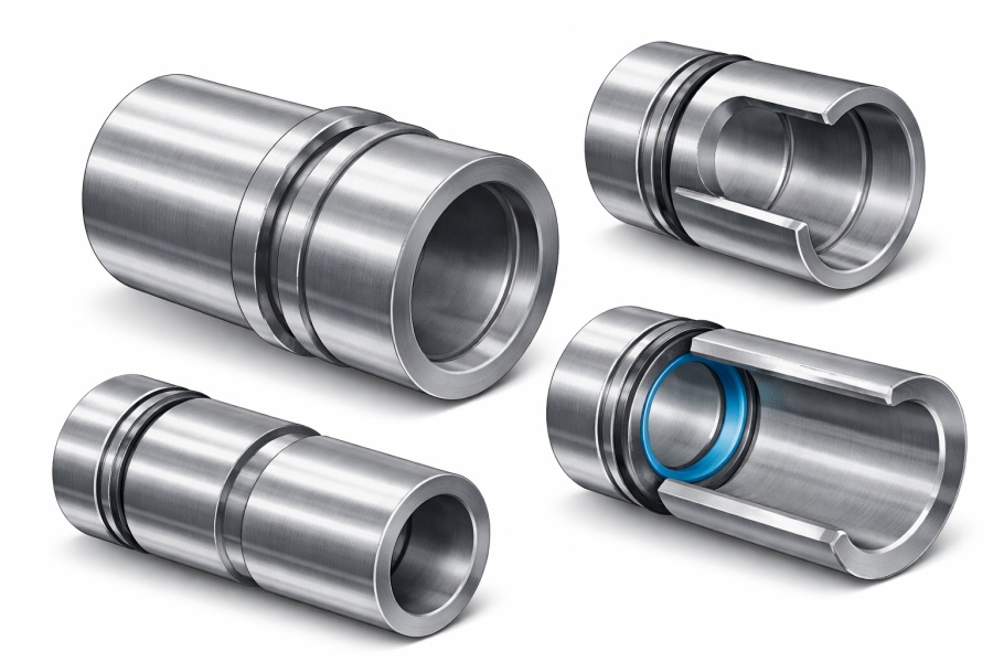
Internal grooving (ID groove machining)
Internal grooving is higher risk: slim tools inside a bore invite vibration and make chip evacuation harder. To keep stability, we prioritize tool rigidity, keep reach short, and apply strategies that avoid chip welding and heat build-up.
Face grooving
Face grooves are often used in sealing interfaces and rotating assemblies. Concentricity and consistent surface finish around the entire ring are critical.
O-ring groove machining
O-ring grooves are unforgiving. A small burr can slice an elastomer during assembly, and a small geometry drift can create leaks. Groove geometry, edge condition, and finish must be controlled as one system.
Parting / cutoff grooves
These operations often define final length and edge condition. Controlling burr and tool stability directly affects assembly and downstream finishing.
Undercut / relief grooves
These reduce interference and protect critical features (threads, shoulders, mating fits). The goal is functional clearance without creating unnecessary stress concentration.
6) What to specify for reliable metal grooving (and what not to force)
If you want consistent metal grooving from a supplier, specify outcomes and inspection expectations—not arbitrary parameter numbers.
What helps (high impact for quality + assembly):
- Groove width / depth tolerance
- Edge condition requirement (break edge / no burr)
- Surface finish requirement if sealing is involved
- Material and hardness condition
- Standard callouts (O-ring groove standard, retaining ring standard)
- Inspection method expectation (pin gauges, optical comparator, CMM strategy)
What usually doesn’t help:
- Forcing a fixed SFM/feed without considering insert geometry, coolant, and machine dynamics
At HDProto, we set groove machining strategy based on material, groove function, rigidity limits, and chip control targets—then validate by measurement and functional checks.
7) RFQ checklist: send this to your supplier (copy/paste)
- Part material and condition (heat-treated? hardness?)
- Groove type (OD / ID / face / O-ring / ring groove / relief)
- Groove dimensions and tolerances (width, depth, location)
- Edge requirement (no burr, edge break value, or specific chamfer/radius)
- Finish requirement in sealing areas (if applicable)
- Quantity and future volume expectation
- File set: STEP/IGES + PDF drawing + any GD&T notes
- Inspection plan expectation (CMM points, go/no-go gauge, ring seating test, etc.)
CNC manufacturing expert with 15+ years of experience. William helps engineering teams turn prototypes into stable production parts through DFM optimization, tolerance planning, machining strategy selection, and inspection-driven quality control.
william@hdproto.comFor any CNC-machined part — whether shafts, housings, brackets, manifolds, or structural components — the foundation of reliable manufacturing starts with clean geometry, well-defined datums, and machining-friendly features that minimize re-clamping risks.
We support function-driven tolerances (down to ±0.01 mm when required) and offer full inspection options including CMM reports, thread gauges, and surface-finish verification to ensure repeatability from prototype to production.
CONTACT OUR EXPERT NOWCase Study 1: Retaining ring groove that stopped failing in assembly
Customer: NordMotion Automation GmbH (Germany)
Engineer: Daniel Kovács, Quality Engineer
NordMotion experienced intermittent assembly failures: retaining rings would not seat cleanly on a motor shaft during final build. Daniel reported that groove width variation was small on paper, but the ring still “hung” and needed manual force.
HDProto’s contribution:
- We reviewed groove edge condition and confirmed the issue was not only width—it was burr + slight edge roll caused by unstable chip formation.
- We revised the grooving strategy to improve chip break and added a controlled edge-conditioning step defined as functional deburr.
- We aligned inspection to function by combining dimensional checks with a ring seating verification method.
Result: Ring seating became consistent, assembly rework dropped, and line complaints stopped.
Case Study 2: O-ring groove stability for a fluid manifold
Customer: Axion Robotics Pte. Ltd. (Singapore)
Engineer: Rachel Lin, Mechanical Engineer
Axion Robotics faced micro-leak issues on an aluminum fluid manifold. Rachel suspected groove depth drift across batches and inconsistent surface finish inside the O-ring groove.
HDProto’s contribution:
- We stabilized groove geometry with a dedicated finishing-pass approach and tighter tool wear monitoring.
- We improved chip evacuation to prevent wall scratching inside the groove.
- We standardized inspection points and verified surface finish specifically at the sealing interface.
Result: Pressure-test leak failures dropped sharply, and the customer moved into repeat orders.
FAQ: Metal Grooving and CNC Groove Machining
1) What is metal grooving in machining?
Metal grooving is the process of machining a controlled channel or recess into a metal part to achieve a function—such as sealing (O-ring groove), retention (retaining ring groove), clearance (relief/undercut), or fluid control (oil/vent grooves). In CNC groove machining, the groove is treated as a functional feature with defined geometry, edge condition, and inspection requirements.
2) What’s the difference between external (OD) grooving and internal (ID) grooving?
OD grooving is performed on the outside diameter of a cylindrical part and is usually more stable because tools have better rigidity and chip evacuation is easier. ID grooving happens inside a bore, where tools are slender, reach is longer, vibration risk is higher, and chip evacuation becomes more difficult—so process stability and tool selection are more critical.
3) Why do grooves fail in assembly even when the dimensions “pass”?
Because groove function depends on more than width and depth. Burrs, edge roll, inconsistent surface finish in the sealing zone, or a measurement method that doesn’t reflect the true functional surface can cause rings to hang up or seals to leak. Groove machining should be verified by inspection aligned to function, not only by calipers.
4) What is the most common cause of leaks in O-ring groove machining?
Two common causes are (1) burrs or sharp edges that damage the elastomer during assembly, and (2) groove geometry drift (width/depth/radius) that changes compression. Surface finish inside the sealing zone also matters—scratches or poor finish can become leak paths under pressure.
5) Should I specify cutting speed and feed rate in my RFQ?
Usually no. Unless you fully control tooling geometry, coolant delivery, and machine rigidity, fixed speeds/feeds can reduce stability. It is more effective to specify outcome controls: tolerances, edge condition, finish requirements (if sealing), material condition, and inspection expectations.
6) What tolerances can HDProto hold for CNC grooving features?
On suitable parts with stable datums and a defined inspection plan, HDProto can typically reach turning tolerance down to 0.005 mm and milling tolerance down to 0.01 mm, depending on material, groove type, geometry, and measurement method. For critical grooves, we recommend confirming functional requirements (seal/ring/clearance) early so the process and inspection match the real use case.
When to choose HDProto for metal grooving work
If you are sourcing metal grooving for CNC turned parts or CNC machined housings, you usually care about repeatability, lead time, and “no surprises” during assembly.
HDProto supports:
- CNC lathe grooving and complex turning features
- CNC milling grooves, channels, and pockets
- Low MOQ + rapid prototyping
- Tight tolerance manufacturing (turning down to 0.005 mm; milling down to 0.01 mm on suitable parts)
- Consistent finishing + deburring standards for seal/retention grooves
Website: https://hdproto.comcom
Email: sales@hdproto.com