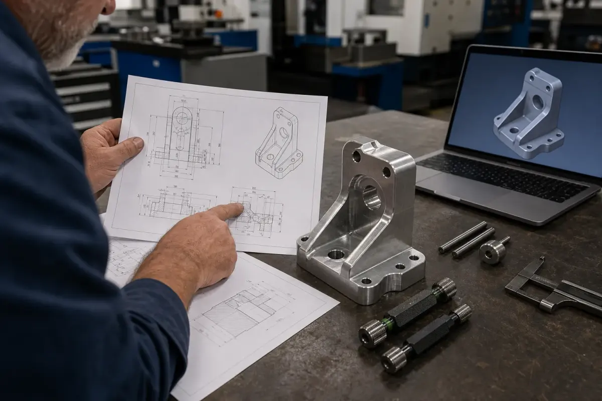
An industrial robot parts DFM checklist saves time because it forces the hard questions before metal is cut. As a CNC machinist, I would rather ask ten questions before programming than explain one failed fit after anodize, plating, or assembly.
Use this checklist alongside our core page for industrial robot parts CNC machining. It is written for engineers, buyers, and automation teams sending parts to a CNC factory.
Key Takeaways
- Put tight tolerances only where the robot function needs them.
- Define datums so machining and inspection agree.
- Plan burr control around cables, bearings, sensors, and grippers.
- Choose materials around load, weight, wear, and finish.
- Send STEP and 2D drawings together for faster quoting.
What Is DFM for Industrial Robot Parts?
DFM for industrial robot parts is the review process that makes a robot component easier, safer, and more repeatable to machine without damaging its function. It covers material, tolerance, datum structure, tool access, wall thickness, surface finish, inspection, assembly, and cost.
The CNC Robot Parts DFM Checklist
| Checkpoint | What to define | Why it matters |
|---|---|---|
| Functional datums | A, B, C datum scheme | Aligns machining, CMM, and assembly |
| Critical fits | Bearing, dowel, shaft, thread fits | Prevents motion and assembly problems |
| Material grade | 6061, 7075, 17-4, POM, PEEK | Controls strength, wear, cost, finish |
| Wall thickness | Minimum walls and ribs | Reduces chatter and distortion |
| Inside radius | Practical cutter radius | Avoids slow tiny tools |
| Edge break | Cable, grip, and handling edges | Prevents cuts and product scratches |
| Surface finish | Anodize, nickel, passivation, Ra | Protects function after coating |
| Inspection | CMM points and gauges | Confirms the right features |
Tolerance: Spend It Where It Works
I often see robot drawings with +/-0.01 mm applied across the whole part. That makes the quote expensive and does not always improve the robot. Tight tolerance belongs on bearing bores, shaft journals, dowel holes, and functional mounting faces. Relief pockets and cosmetic faces can usually be looser.
Material: Do Not Choose by Strength Alone
7075 aluminum is strong, but 6061 may machine, finish, and source better for many EOAT frames. Stainless steel resists corrosion, but it adds weight. POM is light and low-friction, but threads and thin walls need care. PEEK is excellent in demanding environments, but cost is high.
Machinist note: The best material is the one that survives the load, machines repeatably, finishes correctly, and does not make the robot carry unnecessary weight.
Tool Access and Corner Radius
Square internal corners are a common CNC cost driver. A deep R0.2 mm corner may require a fragile tool and long cycle time. If the corner is not functional, give the shop a larger radius. For many robot brackets and housings, R0.5-R2.0 mm is more practical.
Burr Control Is a Design Item
Robot parts often sit near cables, sensors, belts, grippers, and operators. Burrs are not just ugly. They cut insulation, block assembly, damage bearings, and create inconsistent gripper contact.
Add notes for:
- Cable slot edge breaks.
- Thread entry chamfers.
- Bearing shoulder protection.
- Grip-face edge conditions.
- Internal pocket deburring access.
What to Send for a Fast RFQ
- STEP file.
- 2D PDF drawing with critical dimensions.
- Material and finish.
- Quantity and expected repeat orders.
- Assembly notes or photos.
- Critical fits and inspection requirements.
- Robot model, payload, and operating environment if relevant.
FAQ
Do industrial robot parts always need 5-axis CNC machining?
No. Many robot brackets, adapter plates, jaws, and shafts can be made with 3-axis milling, 4-axis milling, or turning. 5-axis machining helps when the part has angled faces, fewer setups, deep access issues, or tight datum relationships across multiple orientations.
What is the biggest DFM mistake in robot parts?
The biggest mistake is unclear function. If the CNC shop does not know which surfaces locate bearings, dowels, shafts, sensors, or grippers, it may spend effort on the wrong features and miss the true assembly risk.
Should I send a 2D drawing if I already have a STEP file?
Yes. A STEP file shows geometry, but the 2D drawing defines tolerances, materials, finish, datums, thread standards, inspection points, and notes. For industrial robot parts, both files reduce quoting mistakes.
Conclusion
Good DFM turns robot parts from risky geometry into repeatable manufacturing work. Define function, datums, tolerances, material, finish, burr control, and inspection before cutting. For project review, start with our industrial robot parts CNC machining page.