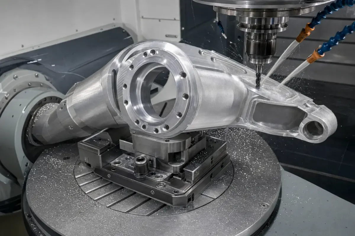
Robot joint housing machining looks simple on the print until the first heavy pocket comes off the machine and the bearing bore starts telling the truth. From the CNC side, a robot joint housing is not just a nice aluminum shell. It is the part that holds the axis, supports the bearing, locates the motor or reducer, and decides whether the robot moves quietly or fights itself.
For buyers comparing industrial robot parts, start with the full machining capability page here: industrial robot parts CNC machining. This article focuses on joint housings from a machinist’s point of view.
Key Takeaways
- Treat bearing bores, dowel holes, and mounting faces as the real control features.
- Rough deep pockets before finishing critical bores.
- Do not over-tolerance cosmetic walls that only add cost.
- Plan hard anodize or nickel thickness before cutting the final fit.
- Inspect the datum relationship, not only single dimensions.
What Is Robot Joint Housing Machining?
Robot joint housing machining is the CNC milling process used to make the structural body around a robot axis. The housing may hold bearings, harmonic drives, gears, motors, seals, cable passages, and mounting faces. Good machining keeps the rotation axis stable, concentric, and square to the robot assembly.
Where the Tolerance Really Matters
On the floor, I separate the drawing into two groups: motion-critical features and everything else. The bearing bore might need H7 or a similar controlled fit. Dowel holes might need +/-0.01 mm positional control. A cover face may only need +/-0.10 mm.
| Feature | Why it matters | Shop-floor control |
|---|---|---|
| Bearing bore | Axis stability and bearing life | Finish boring, bore gauge, CMM |
| Dowel holes | Repeatable assembly location | Ream after stress relief when needed |
| Motor face | Squareness to the axis | Finish pass from stable datum |
| Lightweight pockets | Weight and inertia | Rough first, leave stock, finish later |
| Cable slots | Wire protection | Deburr by design, not only by hand |
Datum Planning Comes Before Cycle Time
The fastest CAM program is not always the best program. For robot joint housings, I prefer a datum-first process. Create one stable face, lock the part repeatably, and keep the bearing bore and mounting pattern tied to that datum.
If a housing has thin walls, deep ribs, and a big bore, roughing can move the part. That is why I leave material around the bore until the heavy cutting is done. A final bore after roughing is often cheaper than chasing a drifting dimension with inspection rework.
Material Notes for Robot Housings
6061-T6 is practical for many automation housings because it machines cleanly and anodizes well. 7075-T6 is stronger, but it can be less forgiving around stress and finishing requirements. For compact high-load joints, stainless steel or alloy steel may be used, but heat, cutter pressure, and cycle time rise quickly.
Machinist note: When a customer says “make it lighter,” I ask where the load path is. Removing metal from the wrong rib saves grams and creates chatter, vibration, or assembly distortion.
Common Mistakes I See in Robot Housing Drawings
- Calling +/-0.01 mm on all surfaces instead of only the locating features.
- Using deep square internal corners that force tiny cutters and long cycle time.
- Forgetting finish thickness on bearing bores and dowel holes.
- Placing cable windows with sharp edges that later cut insulation.
- Missing a clear datum scheme for CMM inspection.
Practical DFM Checklist
- Mark the bearing bore fit and whether the size is before or after finishing.
- Define dowel hole tolerance and assembly direction.
- Add practical inside radii, usually R0.5-R2.0 mm depending on depth.
- Separate cosmetic surfaces from motion-critical surfaces.
- Confirm whether hard anodize, passivation, or plating needs masking.
FAQ
What tolerance is realistic for a robot joint housing?
For critical bores and dowel relationships, +/-0.01 mm to +/-0.03 mm can be realistic after DFM review. Non-critical pockets, covers, and relief faces should use looser tolerances to control cost and lead time.
Should robot joint housings be 6061 or 7075 aluminum?
6061 is cost-effective, stable, and good for many housings. 7075 is stronger and useful for lightweight high-load parts, but it needs more care around stress, corrosion protection, and finishing. The choice depends on load, weight, finish, and budget.
Why do bearing bores go out after pocketing?
Deep pocketing releases stress and removes support around the bore. If the bore is finished too early, the part can move afterward. Rough first, leave stock, then finish the bore from stable datums.
Conclusion
Robot joint housing machining rewards discipline. Start with the motion axis, protect the datum structure, rough before finishing critical features, and inspect the relationships that affect assembly. For CNC support on housings, shafts, EOAT, and adapter plates, review our industrial robot parts machining page.