Two Curved CNC Parts,
One Near-Seamless Assembly
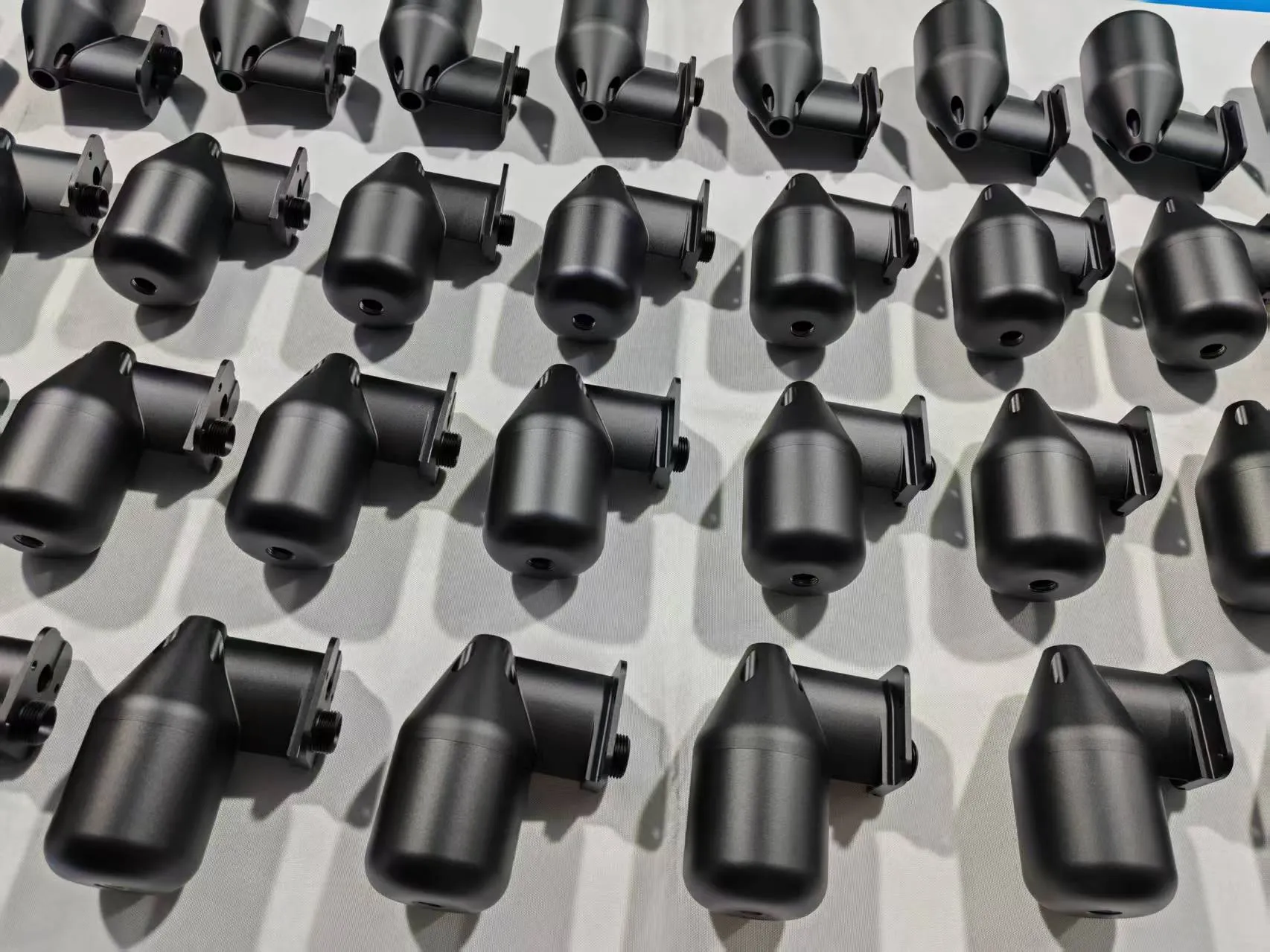
Five-axis curved surface machining brought two independently manufactured components together with a barely visible joint, preserving the continuous silhouette of a one-piece part.
- Process
- 5-axis curved surface machining
- Key challenge
- Matching two mating contours
- Assembly result
- Near one-piece appearance
The Customer Requirement
A two-part construction that should look like one
The requirement for this project went beyond producing a smooth curved component. Two separate parts had to meet closely after assembly, with an exterior that read as a single continuous form. Five-axis curved surface machining was the specified process; the defining challenge was the fit between the two components.
Along a curved joint, the eye follows the surface from one part to the next. A local gap, a height mismatch, or a change in contour can interrupt that transition. The difficult part is therefore not just machining each curve, but making the two curves agree where they meet.
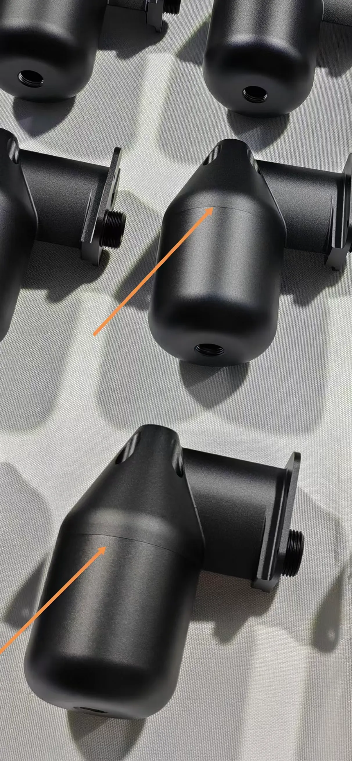
The supplied close-up identifies this exact interface with orange arrows. The joint remains visible on close inspection, but it is fine enough for the assembled exterior to appear almost one-piece. That close-fitting transition is the central result of this case.
Engineering Focus
The fit matters as much as the surface
This case illustrates why assembly requirements belong in the machining review. For a similar project, these are the key engineering questions to resolve before production.
01
Treat both parts as one assembly
The mating profile and visible exterior need to be reviewed together. A part can satisfy its individual dimensions yet still create a visible step when paired with its counterpart. The assembly relationship is the starting point for defining critical features.
02
Protect the curved profile
Five-axis access supports machining around changing surface directions. For a close-fitting curved assembly, tool access, surface transitions, and the relationship between the exterior and mating geometry all deserve attention during process planning.
03
Control the joint without softening the edge
Burrs can prevent proper seating, while excessive edge breaking can make a fine joint look wider. Deburring and any finishing allowance need to preserve the intended mating edge rather than treating it as a generic external corner.
04
Review the assembled appearance
Individual-part inspection and assembly evaluation answer different questions. A drawing-based review should cover both fit and the visible transition under agreed viewing conditions, including any local opening or offset along the curved joint.
The Result
A fine joint. A continuous curved exterior.
The project photographs show assembled components with closely matched contours and a subtle joining line. Instead of looking like two unrelated pieces, the parts form a coherent outer shape with a near one-piece appearance.
For the customer, the achievement is the combination: complex curved geometry and an assembly interface that preserves the intended appearance. The batch photograph also shows the finished assemblies together, while the annotated detail makes the joint easy to locate.
“Near-seamless” describes the visible fit, not a zero-clearance measurement, a monolithic construction, or a sealing rating. Material grade, surface treatment, measured gap, quantity, and inspection records were not provided for publication.
Discuss A Similar Project
Need curved parts that fit as one?
Send both component models and your assembly requirements. Huade can review the curved geometry, mating interface, and acceptance criteria before quoting.
Request an assembly reviewInclude with your RFQ
- 3D models for both components, preferably in their assembled positions.
- A controlled drawing identifying mating datums and critical fit dimensions.
- Required joint clearance, allowable surface offset, and cosmetic viewing conditions.
- Material, finish, quantity, and any inspection-report requirements.