Turned and Milled Components / Product Video Case Note
CNC Turned Components Case Note: A Flanged Shaft
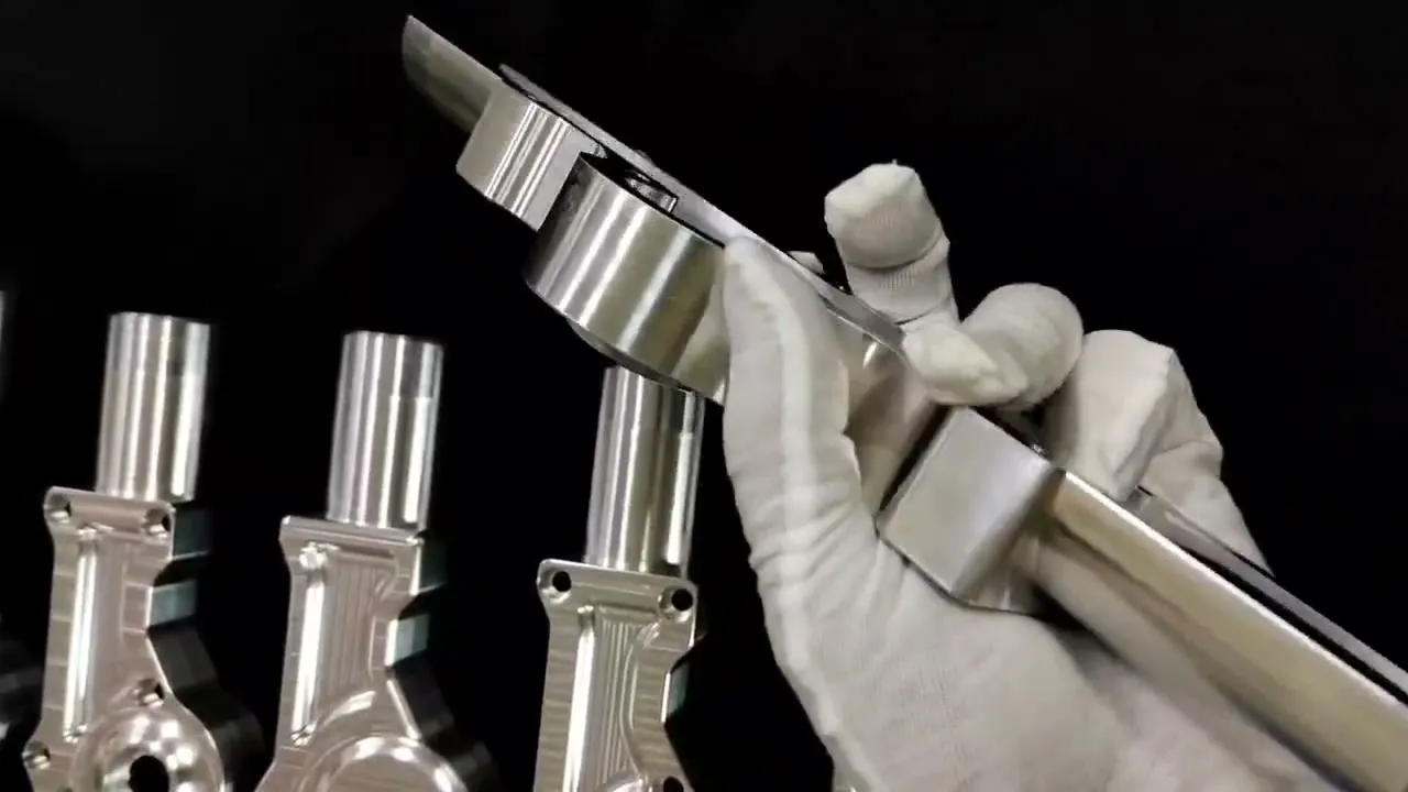
Watch original footage of long shaft components with stepped round sections and mounting ears. Review turning, secondary features, datums and RFQ requirements.
EvidenceOriginal product video and extracted stills
Engineering focusTurned and Milled Components
Not verified by the footageAlloy, tolerance, customer or test outcome
What the Product Video Shows
This case note separates direct observations from manufacturing questions. The source is a product presentation, not a customer acceptance report or a complete process record.
OBSERVATION 1
Round and non-round geometry
The operator presents a long cylindrical component with stepped sections and a flange-like mounting region. Several similarly shaped components are visible behind the one being handled.
OBSERVATION 2
Mounting ears and holes
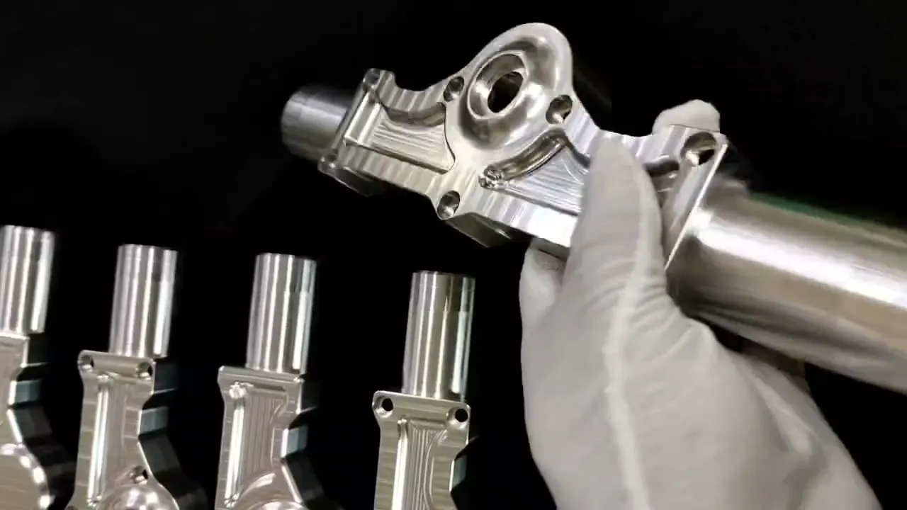
As the part rotates, the flange outline and its openings become visible. The clip supports discussion of mixed geometry, but does not identify the material grade or show the cutting sequence.
OBSERVATION 3
Multiple visible pieces
The background provides a visual view of more than one component. It does not establish order quantity, dimensional consistency, production yield or delivery history.
Engineering interpretation, not measured results
What to Resolve Before Machining a Similar Part
Connect secondary features to the shaft axis
Rotational sections are a natural subject for a turning review, while mounting ears and off-axis holes require additional operations. Ask how the proposed route preserves the drawing relationships between those features.
Review support for the long section
A long component merits a workholding discussion covering support, clamping marks and access. Select the arrangement for the actual dimensions and material; neither is available from this video alone.
Keep fit and appearance requirements separate
Identify bearing or locating seats if present in the intended design, then specify their controls. Separately define permitted marks on handled surfaces. A reflective appearance is not evidence of a measured roughness value.
RFQ and Acceptance Checklist
| Feature | Question to resolve | Evidence to agree |
|---|---|---|
| Stepped diameters | Which surfaces locate or rotate in the assembly? | Actual size and required runout or form results |
| Flange face | How does it reference the working axis? | Agreed orientation and face-geometry inspection |
| Mounting holes | What controls position relative to the shaft? | Datum-referenced hole inspection and required thread checks |
Possible Applications and Evidence Limits
Comparable shapes may be used in mechanical linkages, equipment supports or motion assemblies. The actual application, loading and customer are not confirmed by the source footage.
No material certificate, controlled drawing, dimensional report or customer acceptance record accompanies this clip. Material grade, process route, achieved tolerances, production quantity and delivery performance are therefore not claimed. A similar part requires its own feasibility review.
Review a Similar Component
Send the CAD model, drawing revision, material grade, quantity, finish and critical-feature list. Include the assembly function and the reports needed for acceptance.
Request a Drawing Review