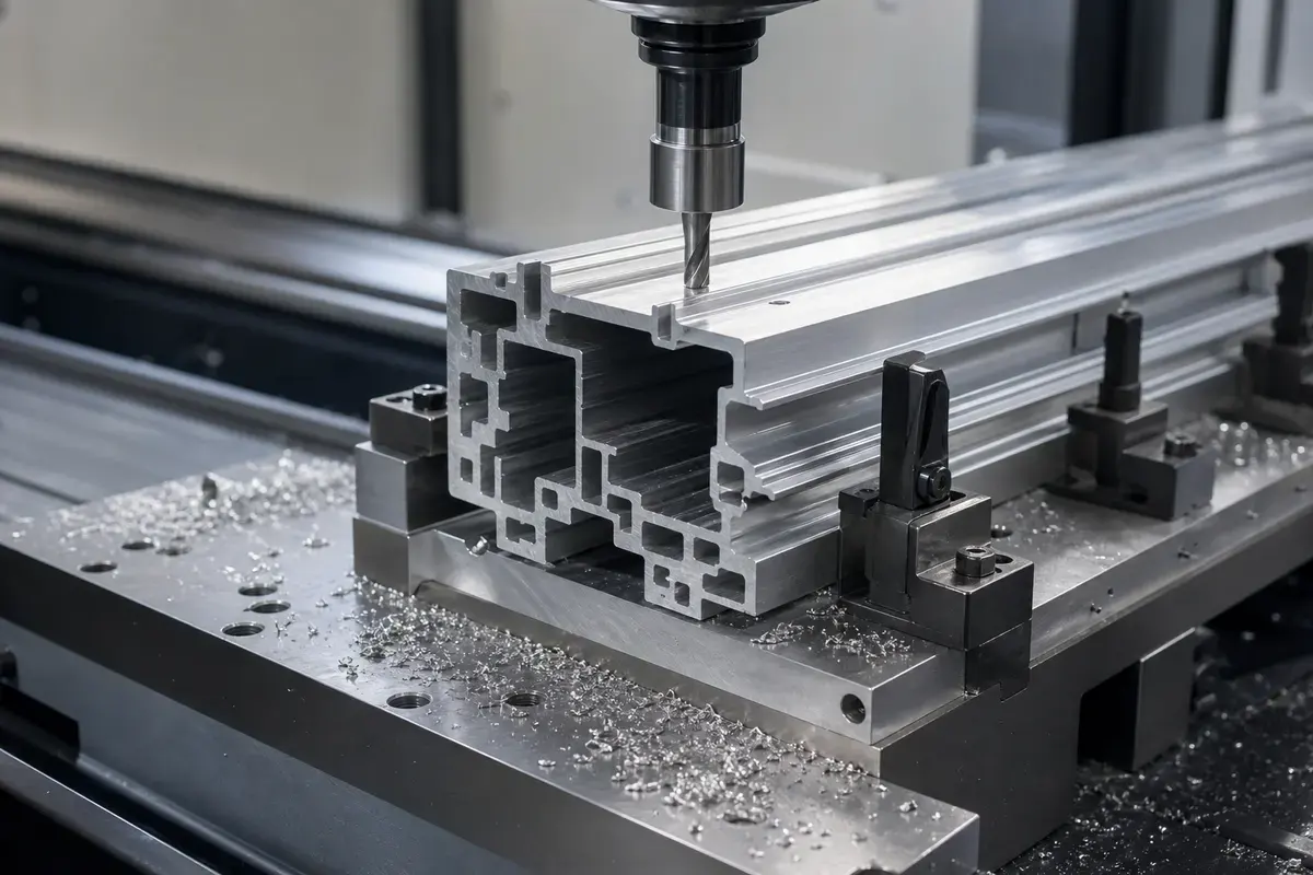
Cut aluminum extrusion with a carbide saw when the requirement is a clean blank or loose final length. Add CNC machining when the part needs controlled end faces, hole position, threads, slots, pockets, bearing seats, or datums tied to the extruded profile. The economical route is often extrude near-net shape, saw to blank length, then machine only the functional features.
That hybrid route can save material and machining time, but extrusion is not a precision-machined surface. Bow, twist, wall-thickness variation, die lines, corner radii, and residual stress must be considered in the fixture and drawing.
Saw cutting vs CNC machining
| Requirement | Saw only | Saw plus CNC machining |
|---|---|---|
| Loose finished length | Good fit | Usually unnecessary |
| Square, controlled end face | Possible with a capable saw; verify tolerance | Better control and repeatability |
| Holes or slots located to profile datums | Limited | Good fit |
| Tapped holes and counterbores | Secondary operation required | Integrated into machining setup |
| Bearing or sealing interface | Rarely sufficient | Machine and inspect |
| Cosmetic anodized housing rail | Possible after deburring | Machine interfaces before anodizing |
Hydro describes extrusion as a process that creates profiles with tailored cross-sections. That geometric efficiency is its strength: internal channels, ribs, screw bosses, and mounting rails can be formed along the entire length. CNC machining then localizes features that cannot run continuously.
Start with an extrusion-aware drawing
Separate the drawing into three feature types:
- As-extruded surfaces governed by the extrusion profile and applicable tolerances.
- Saw-cut surfaces governed by blank-length and squareness requirements.
- Machined surfaces governed by CNC datums, dimensions, GD&T, and finish.
Do not place machined tolerances on every as-extruded wall. If a hole pattern must align to an internal channel or T-slot, select functional datums that the fixture and inspection method can access. Profile variation may need to be absorbed by floating locators or custom jaws rather than forced flat.
Control distortion and workholding
Long, thin extrusions can bow under their own residual stress or from uneven clamping. A fixture that pushes the profile into an artificial shape can produce an acceptable part while clamped and an out-of-tolerance part after release.
Process planning may include:
- Supporting the profile near cutting forces without over-constraining it.
- Using custom jaws that locate the stable geometry.
- Roughing and finishing critical faces in a controlled sequence.
- Measuring free-state requirements after unclamping.
- Allowing straightening only when the specification and risk support it.
For complex prismatic rails, housings, and plates, Huade’s CNC milled parts capability covers multi-axis machining and inspection. The main aluminum machining page lists common alloys and prototype-to-production support.
Alloy and temper choices
6063 is widely associated with extruded profiles and cosmetic applications. 6061 offers a useful strength-machinability balance and is also available in extruded forms. The correct temper and applicable extrusion standard belong on the purchase specification.
If the part will be heavily machined from a thick block rather than use the near-net profile, an extrusion may no longer offer the best material yield or stability. Compare billet, plate, and extrusion based on final geometry, volume, sourcing, and critical properties—not on shape alone.
End quality, burrs, and chips
A saw-cut end can have burrs, tooth marks, and sharp edges. Milling improves the controlled face but can still leave burrs at thin fins, slots, and intersecting holes. Define edge breaks where assembly, cables, seals, or human handling make them important.
Avoid vague instructions such as “remove all sharp edges” on a precision interface. State the maximum edge break or identify protected edges. Our aluminum deburring guide compares manual, mechanical, thermal, and toolpath-based considerations for machined aluminum parts.
Plan anodizing before machining release
Anodized appearance varies with alloy, temper, surface condition, and lot. As-extruded faces and freshly machined faces can look different after the same anodizing cycle. For appearance-critical products, establish acceptable samples and keep visible surfaces consistent where possible.
Mask grounding pads, tight fits, or threads when the functional design requires it. Include finished-dimension expectations in the drawing and review our anodizing service before releasing the machining tolerances.
RFQ package for an extruded part
Send the final part model, profile drawing or source, alloy and temper, extrusion length, machined-feature drawing, straightness or twist requirements, visible surfaces, anodizing specification, and annual demand. State whether Huade should source the extrusion or machine customer-supplied stock.
For a real extrusion-to-machined-part program, see the IP67 energy-storage enclosure case study. If your extrusion needs precision end work, holes, slots, or sealing features, send the profile and finished-part drawings for review.
Technical sources
- Hydro: Extruded Aluminium Profiles — extrusion process and profile-design context.
- The Aluminum Association: The Aluminum Advantage — aluminum properties, standards, and industry resources.
- Aluminum Anodizers Council: Anodizing Design — alloy, temper, appearance, and anodizing design considerations.