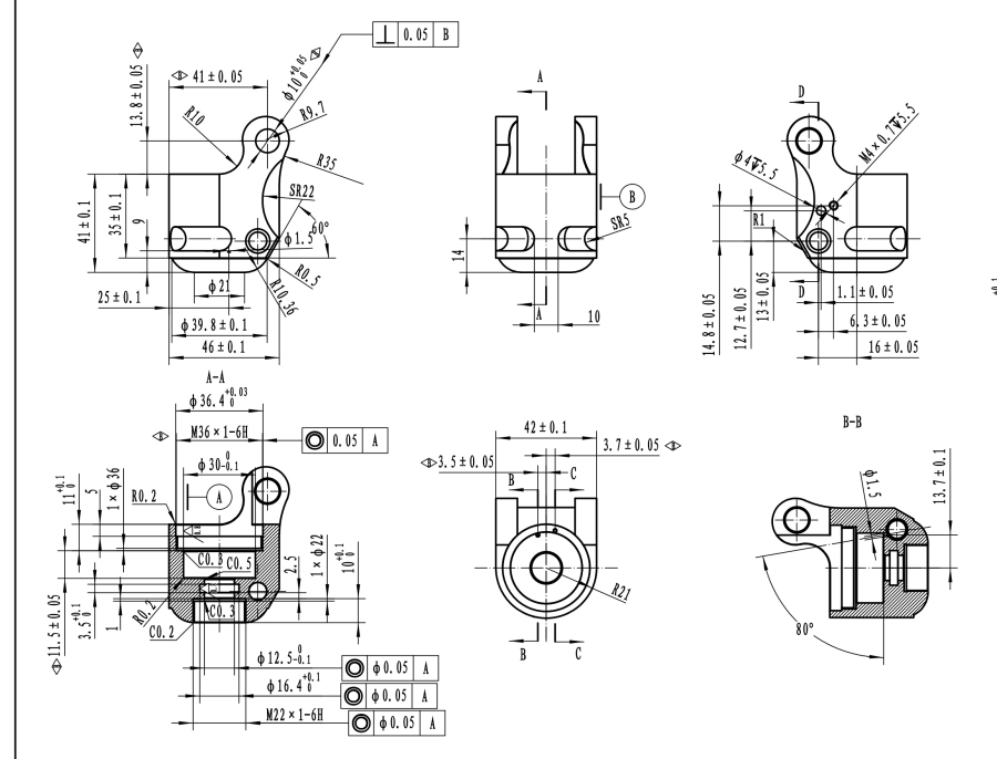
Machining blueprint symbols—also called CNC blueprint symbols, blueprint machining symbols, or machine blueprint symbols—form the core language of engineering drawings. Whether you are reviewing a spec drawing, preparing a CNC project, or communicating manufacturing requirements to a supplier, these standardized symbols ensure accuracy, consistency, and clear engineering intent.
At Dongguan Huade Precision Manufacturing Co., Ltd. , our engineering team reviews thousands of blueprints each month. A correct interpretation of machining blueprint symbols ensures consistent ±0.01 mm precision, fast quoting, reduced errors, and reliable prototype-to-production workflows.
This comprehensive guide combines essential blueprint symbols, GD&T features, surface finish marks, and blueprint reading essentials into one complete reference.
What Are Machining Blueprint Symbols?
Machining blueprint symbols — standardized icons used across CNC engineering drawings — define key manufacturing requirements such as:
- Dimensions
- Tolerances
- Hole features
- GD&T controls
- Surface finishes
- Depth and radius details
- Manufacturing instructions
Machining blueprint symbols create a universal manufacturing language that ensures machinists, engineers, QC inspectors, and suppliers interpret drawings accurately and consistently — reducing errors and improving production efficiency worldwide.
Why Machining Blueprint Symbols Matter in CNC Manufacturing
Correct interpretation influences:
✔ Machining strategy
(tool paths, cutter selection, tolerances to hold)
✔ Inspection method
(CMM, micrometers, gauges)
✔ Blueprint-to-part accuracy
(reduces rework and ensures functional assembly)
✔ Manufacturing cost and quoting
(tight tolerances and surface finish raise cost)
✔ Communication efficiency
(eliminates misunderstandings between engineers and machinists)
At Dongguan Huade Precision Manufacturing Co., Ltd., every drawing undergoes complete DFM review, tolerance check, and GD&T feasibility verification before machining begins.
Common CNC Blueprint Symbols and Their Meanings
This section covers the most common CNC blueprint symbol topics engineers frequently search for, including:
- machining blueprint symbols
- blueprint symbols for machining
- blueprint machining symbols
- cnc blueprint symbols chart
- machining blueprint symbols list
- machining blueprint symbols pdf
Below is your complete reference list of blueprint symbols and their meanings.
3.1 Dimensional Symbols (Found on Most Spec Drawings)
Symbol
Meaning
Ø
Diameter (common on turning & drilling drawings)
R
Radius
↧
Depth
±
Bilateral tolerance
+0/-0.02
Unilateral tolerance
↔
Linear dimension direction
↕
Vertical dimension
3.2 Hole & Feature Symbols
Symbol
Meaning
⌴
Counterbore (CB)
⌵
Countersink (CSK)
⌓
Spotface
M6 × 1
Metric thread
¼-20 UNC
Imperial thread
These appear in all blueprint symbols for machining and are essential for CNC drilling and milling.
3.3 Surface Finish Symbols (Ra)
Symbol
Meaning
Ra 3.2 μm
Standard machining finish
Ra 1.6 μm
Fine finish
Ra 0.8 μm
Precision sealing surface
Ra 0.4 μm
Mirror/optical finish
/
No machining required
/\
Surface must be machined
Surface finish symbols are critical in machining blueprint symbols charts.
3.4 Complete GD&T Symbols
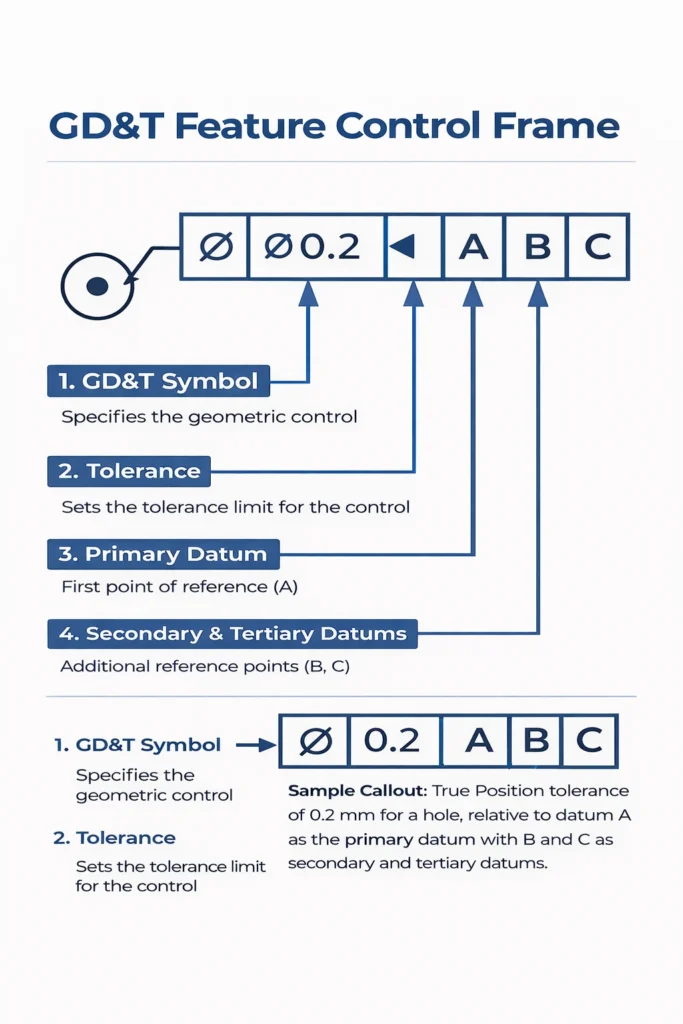
Example of a GD&T feature control frame used in CNC machining blueprints.
These appear on almost all spec drawings requiring precision.
Symbol
Meaning
⌖
True Position
∥
Parallelism
⟂
Perpendicularity
○
Circularity
⌭
Cylindricity
⌯
Runout
⌰
Total Runout
∡
Angularity
⌒
Profile of a Line
⌓
Profile of a Surface
□
Datum Feature
⫽
Flatness
≡
Feature Control Frame
Related topics engineers often search for include:
✔ blueprint machining symbols
✔ complete GD&T symbols
✔ machining blueprint symbols chart
Blueprint Reading Essentials
When reading a CNC blueprint, always locate:
✔ 1. Title Block
Material, finish, tolerances, revision level.
✔ 2. Datum Scheme
Defines which surfaces control measurements.
✔ 3. GD&T controls
Critical for fit, alignment, and assembly.
✔ 4. Hole & thread notes
Often include hidden requirements like chamfers or deburring.
✔ 5. Section, detail, & auxiliary views
Provide clarity on complex features.
✔ 6. General Tolerances
Often found in the drawing notes.
Understanding these blueprint reading symbols helps engineers and buyers avoid costly misunderstandings.
What a CNC-Ready Drawing Must Include
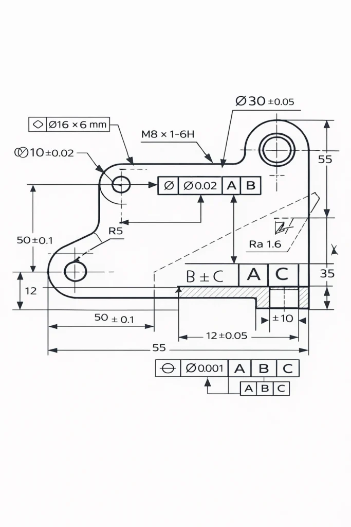
Sample machining blueprint with GD&T, tolerances, datums, and standard machining symbols.
A complete, manufacturer-ready spec drawing contains:
- 2D PDF drawing
- 3D STEP model
- All dimensions clearly defined
- Tolerances and GD&T
- Surface finish marks
- Hole/thread tables
- Material & hardness
- Notes on chamfers, deburring, sharp edges
- Heat treatment, coating, or surface finish instructions
This dramatically reduces quoting time and prevents mistakes.
From Blueprint to Machining
We use blueprint symbols throughout our process:
✔ DFM Review
Confirm tolerance feasibility and tool access.
✔ Machining Plan
Tool paths, fixturing, and process sequence.
✔ In-Process QC
Measurement at key stages.
✔ Final Inspection
CMM, pin gauges, micrometers.
✔ Optional Full Inspection Report
For aerospace, medical, and high-precision industries.
Our 3-axis, 4-axis, and 5-axis machining centers deliver ±0.01 mm accuracy with 2–3 day rapid prototyping.
Download the Machining Blueprint Symbols PDF
We created a printable machining blueprint symbols PDF that includes:
✔ Full symbol list
✔ Surface finish chart
✔ GD&T reference table
✔ Blueprint reading guide
Download PDF Guide (Free)
📥**Machining Blueprint Symbols PDF Guide**
This downloadable guide also helps engineers searching for topics like:
- machining blueprint symbols PDF
- CNC blueprint symbols PDF
- blueprint symbols machining chart
Apply the Symbols to Your RFQ
CNC blueprint symbols are the universal language of manufacturing. Understanding dimensional symbols, GD&T features, surface finish marks, and blueprint reading rules ensures:
- Accurate communication
- Lower machining cost
- Faster quoting
- Fewer production errors
- Better engineering-to-manufacturing alignment
At Dongguan Huade Precision Manufacturing Co., Ltd., we help global customers interpret drawings, optimize designs, and manufacture high-precision CNC parts with world-class consistency.
Have a blueprint, STEP file or technical drawing? Send it through our RFQ form with the material, quantity and critical tolerances. You can also review our GD&T guide, machining tolerance guide and tap drill calculator.