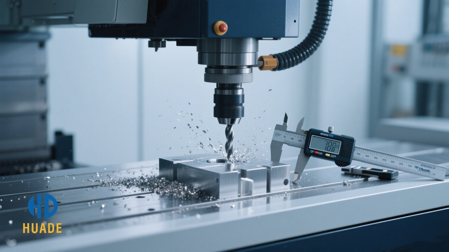
Micron-level CNC machining accuracy is not produced by a machine specification alone. Thermal drift, workholding distortion, tool deflection, tool wear, material behavior, programming and measurement uncertainty all affect the result.
The useful question is not “Can this shop hold a micron?” It is “Which feature needs which tolerance, under what conditions, and how will the result be verified?”
| Requirement | Practical engineering response |
|---|---|
| Tight size on one accessible feature | Stabilize temperature, use a controlled finishing pass and verify with a suitable gauge |
| Tight relationship between several datums | Plan setups around the datum structure and verify on a capable CMM |
| Thin walls or long spans | Control clamping force, cutting load and post-machining movement |
| Tolerance required after coating | Define whether dimensions apply before or after finishing and account for coating buildup |
| Micron-level claim without inspection method | Agree on equipment, uncertainty, temperature and sampling before quoting |
Start with the Functional Requirement
Convert a general precision request into specific drawing requirements:
- Which fit, seal, bearing or alignment depends on the dimension?
- Which surfaces establish the datum reference frame?
- Does the tolerance apply in the free state or while assembled?
- Does it apply before or after heat treatment or coating?
- What temperature and measurement method define acceptance?
Applying a very tight tolerance to every feature increases manufacturing and inspection effort without necessarily improving function.
Thermal Drift
Machines, tools and workpieces change dimension as temperature changes. The effect grows with feature length and the thermal expansion of the material.
Useful controls include warm-up routines, stable finishing conditions, temperature-aware measurement and allowing a part to stabilize before final inspection. The required level of control depends on the tolerance, feature span and material.
Workholding Distortion
A part can meet the drawing while clamped and move after release. Thin walls, long spans and soft materials are especially sensitive.
The process plan should consider:
- clamping location and force;
- roughing and finishing sequence;
- stress relief or intermediate stabilization where appropriate;
- free-state inspection requirements;
- support near critical features.
Tool Deflection and Wear
Long tools, deep pockets and aggressive cutting loads can move the cutting edge away from the programmed path. Tool wear can also change size and surface finish over a production run.
Use rigid tool access, controlled finishing allowances, appropriate cutting data and defined tool-life rules. For important dimensions, verify the feature early enough to correct the process before the batch is complete.
Datum Strategy and Setup Count
Many accuracy problems are relationship problems rather than simple size problems. Moving a part between setups introduces new location and orientation uncertainty.
Where practical, machine related features in one setup or transfer them from stable, inspectable datums. The drawing and process plan should use the same functional datum logic.
Measurement Uncertainty
Inspection equipment must be capable of resolving the tolerance with suitable uncertainty. A CMM, bore gauge, micrometer, optical system and surface profilometer answer different questions.
Before production, agree on:
- the measurement method;
- fixture and datum alignment;
- part temperature and condition;
- sampling frequency;
- rounding and acceptance rules;
- the report required by the buyer.
A machine tool position display is not proof that the finished feature meets its drawing tolerance.
Process Capability Across a Batch
One conforming first article does not prove a stable production process. Batch control may require tool-life limits, in-process measurements, control features and sampling linked to actual failure risk.
The inspection plan should distinguish between:
- setup approval;
- in-process control;
- final acceptance;
- periodic capability confirmation.
Not every feature requires the same inspection frequency. Concentrate evidence on the characteristics that control assembly and performance.
When Very Tight Tolerances Are Realistic
Feasibility depends on the complete feature, not only the number in the title block. A small accessible bore in stable material presents a different problem from a long thin wall after coating.
A supplier should review geometry, feature size, material, heat treatment, finishing state, batch size and measurement method before committing to a tolerance.
Tolerance Feasibility Questions for an RFQ
Use the functional requirement to decide where precision effort belongs. The same numerical tolerance can be routine on one feature and expensive or unreliable on another.
| Feature situation | Question to resolve before production |
|---|---|
| Bearing bore or locating diameter | Which datum controls it, and which gauge or CMM strategy proves it? |
| Thin wall or long unsupported span | Is the requirement measured while clamped, free-state or assembled? |
| Pattern of holes across multiple faces | Can related features stay in one setup, or is a transfer datum required? |
| Dimension after anodizing, plating or heat treatment | Does the drawing apply before or after the process, and what buildup is allowed? |
| Repeated production feature | What sampling, tool-life and reaction plan catches drift before the batch is complete? |
When these choices are visible in the drawing, suppliers can quote the right control plan instead of adding blanket precision to every feature. See the CNC machining tolerance guide for how dimensional and geometric requirements work together.
Engineering Takeaways
Define the functional features, datum reference frame, material condition, finishing state and inspection method before production. Avoid treating “micron-level” as a universal requirement.
For a project review, see our tight-tolerance CNC machining service, CMM inspection guide and quality system.