Complex Housing / Product Video Case Note
Precision Machining Case Note: A Complex Bore Housing
Original product footage of a machined housing with a large central bore, recessed pockets and mounting features, with practical datum and inspection questions.
EvidenceOriginal product video and extracted stills
Engineering focusComplex Housing
Not verified by the footageAlloy, tolerance, customer or test outcome
What the Product Video Shows
This case note separates direct observations from manufacturing questions. The source is a product presentation, not a customer acceptance report or a complete process record.
OBSERVATION 1
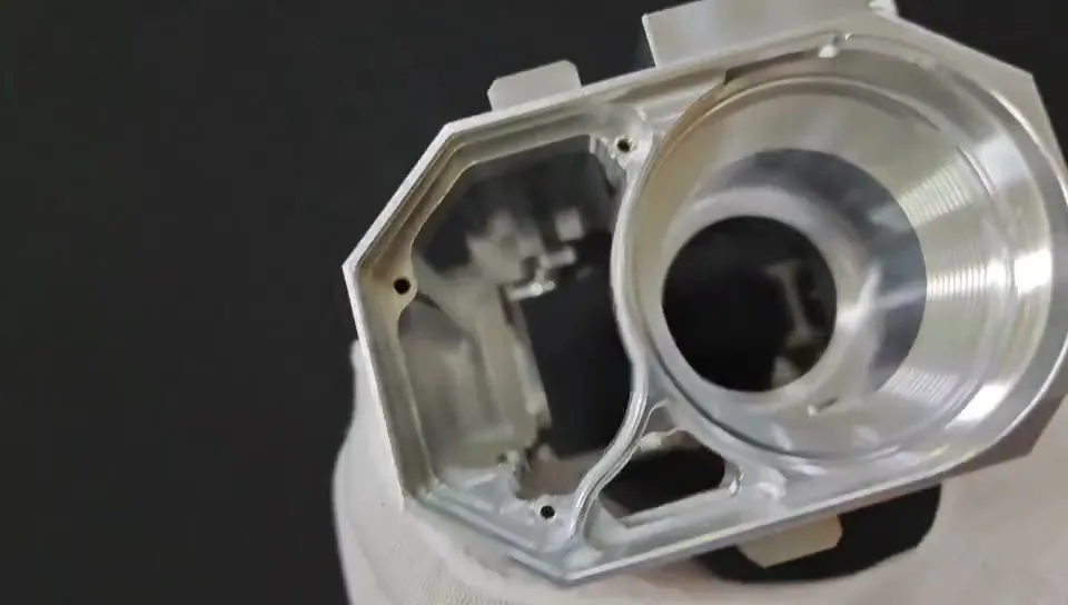
Large circular interface
The footage shows a central circular opening with stepped surrounding surfaces. The operator turns the component to reveal the opposite side; the video does not provide dimensional measurements.
OBSERVATION 2
Pockets beside the bore
Recessed regions, internal walls and perimeter holes sit around the main opening. Visible tool paths and transitions help communicate the geometry more clearly than a single front photograph.
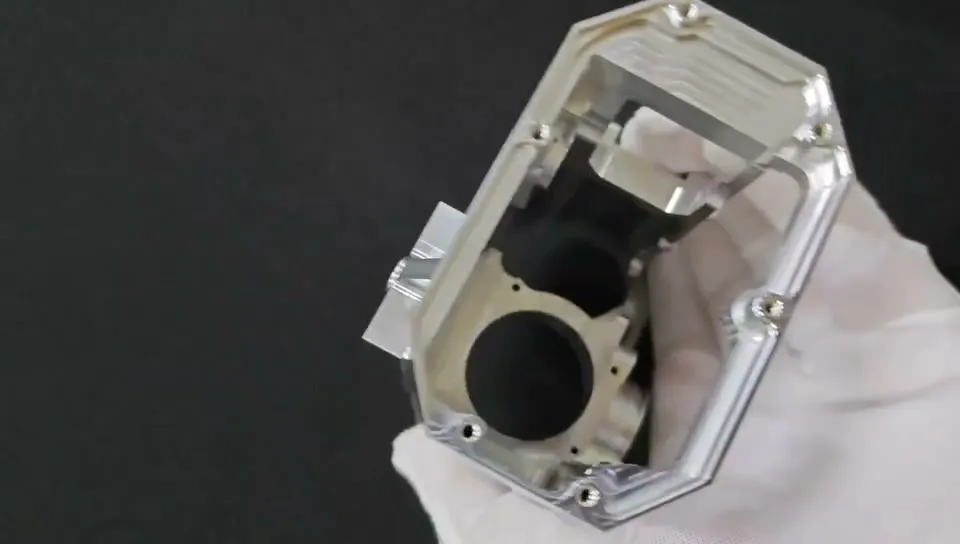
OBSERVATION 3
Features on several faces
The changing view reveals exterior steps and side features. It is a finished-part presentation, not a recording of the complete machining sequence or an inspection operation.
Engineering interpretation, not measured results
What to Resolve Before Machining a Similar Part
Define the functional datum system
If the bore locates another component, the drawing should identify how mounting faces and holes relate to it. Bore size alone would not establish the position or orientation of the surrounding interfaces.
Review pocket access and workholding
The combination of recessed geometry and multiple faces makes tool access and support worth reviewing. A proposed route should explain how the part is referenced after repositioning; the footage does not establish the machine axis count.
Inspect in the accepted finished state
If finishing is required, identify masking and the dimensions that apply afterward. For thin local walls, agree on support during measurement instead of relying on a clamped reading that may not represent assembly.
RFQ and Acceptance Checklist
| Feature | Question to resolve | Evidence to agree |
|---|---|---|
| Central bore | What locates in it, and which size and geometry controls apply? | Drawing-linked bore measurements and applicable geometric results |
| Mounting faces and holes | Which features establish the assembly reference? | Datum-based inspection of the agreed relationships |
| Pocket edges and finish | Which edges must be broken, protected or masked? | Agreed edge, surface and finished-condition checks |
Possible Applications and Evidence Limits
This geometry is relevant to engineering discussions about drive housings, instrument bodies and other assemblies with a central interface. Those are possible applications, not an identification of the product or its customer.
No material certificate, controlled drawing, dimensional report or customer acceptance record accompanies this clip. Material grade, process route, achieved tolerances, production quantity and delivery performance are therefore not claimed. A similar part requires its own feasibility review.
Review a Similar Component
Send the CAD model, drawing revision, material grade, quantity, finish and critical-feature list. Include the assembly function and the reports needed for acceptance.
Request a Drawing Review