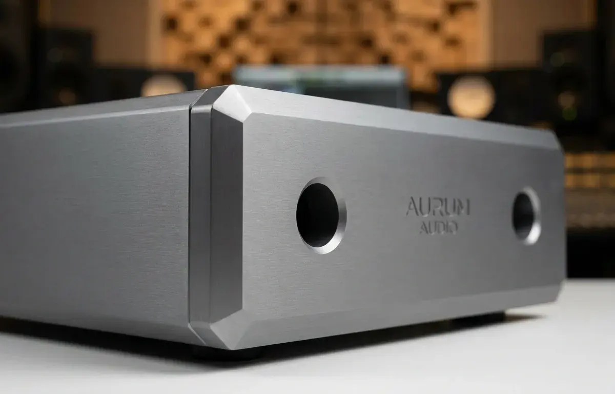
CNC machined aluminum parts are used when a product needs a custom geometry, dependable dimensions, lower weight than steel, and a finish suitable for industrial or visible hardware. They appear in housings, brackets, fixtures, heat sinks, automation equipment, UAV structures, audio components, and many prototype assemblies.
The material is familiar, but purchasing a successful aluminum part still requires decisions about process, alloy, tolerances, finish, inspection, and quantity. This guide gives buyers a practical starting point before they request quotes.
What are CNC machined aluminum parts?
They are components made by removing material from aluminum stock with computer-controlled equipment. Depending on the geometry, the manufacturer may use CNC milling, CNC turning, or a combined mill-turn process.
CNC machining is especially useful when the part needs detailed pockets, threads, precision holes, contoured surfaces, tight relationships between several faces, or a small-to-medium production quantity. It does not require dedicated production tooling in the way casting, stamping, or injection molding does, which makes it a practical route for prototypes, bridge production, and repeat custom components.
Common CNC processes for aluminum
CNC milling
CNC milling is used for prismatic parts: plates, brackets, housings, frames, manifolds, heat sinks, and components with pockets, slots, faces, and drilled holes. Three-axis milling suits many parts; four- or five-axis setups can reduce re-clamping where features sit on multiple faces or require angled access.
CNC turning
CNC turning is used for round or rotational parts such as spacers, shafts, bushings, sleeves, threaded connectors, and flanges. Live tooling can add milled flats, cross holes, or other secondary features in the same route when the geometry supports it.
Post-machining operations
A complete part can also need deburring, threaded inserts, anodizing, bead blasting, laser marking, cleaning, assembly, and inspection. Treat these as part of the part specification, not separate assumptions. A good RFQ describes which of them are required.
Common aluminum grades for CNC parts
For many custom parts, 6061-T6 is the first alloy considered because it balances strength, corrosion resistance, availability, machining, and finishing. 7075-T6 is a common next step for higher-strength, weight-sensitive designs. Other aluminum grades may suit sheet-derived work, extrusions, marine exposure, or a specific industry standard.
Choose the alloy from the part’s actual job: load, stiffness, temperature, environment, joining method, electrical or thermal requirement, finish, and cost target. Do not use “aluminum” as the complete drawing callout. Our 6061 vs. 7075 guide explains the most common material decision in more detail.
Typical applications
Aluminum CNC machining is a strong fit for:
- Electronics: enclosures, panels, heat sinks, sensor mounts, and thermal interfaces.
- Automation and robotics: end-effectors, adapter plates, locating fixtures, guards, and motor mounts.
- Aerospace and UAV projects: lightweight brackets, payload mounts, structural interfaces, and ground-support fixtures.
- Industrial equipment: jigs, test fixtures, machine components, covers, and low-volume replacement parts.
- Consumer and audio products: controls, chassis, knobs, cosmetic housings, and mounting structures.
Application labels alone do not define the manufacturing route. A “housing,” for example, may need only general dimensions, or it may contain a sealing groove, bearing bore, heat path, threaded cover interface, and cosmetic anodized exterior. The drawing should identify the functional features.
Tolerances: specify what the assembly needs
Aluminum can support precise CNC work, but every tighter dimension adds process and inspection effort. Mark the dimensions that control fit, motion, location, leakage, or appearance. Examples include bearing bores, dowel-hole patterns, sealing faces, threaded interfaces, and critical datums.
Do not use a blanket tight tolerance where a clearance feature can be looser. This makes the drawing easier to inspect and helps the manufacturer focus control where it matters. If the part has multiple related features, define a datum scheme and use GD&T where it communicates the assembly requirement better than a collection of plus/minus dimensions. Our precision aluminum machining guide covers the manufacturing consequences of wall thickness, datums, and inspection.
Aluminum surface finishes
The most common choices are:
| Finish | Typical reason to choose it | Design consideration |
|---|---|---|
| As-machined | Functional parts and hidden surfaces | Tool marks remain visible |
| Bead blasted | Uniform matte texture | Changes appearance; protect critical dimensions |
| Anodized | Appearance, corrosion resistance, selected wear needs | Plan for threads, press fits, masking, and color variation |
| Powder coated | Durable colored coating for suitable geometry | Adds coating thickness and can soften fine details |
| Polished | Reflective or premium cosmetic appearance | More labor-sensitive; define the visual expectation |
Select the finish by function and environment. Finishing should be agreed before the first article, especially for close-fitting, sealing, electrical-contact, or highly cosmetic areas.
What drives lead time and price?
The biggest inputs are material availability, part size, amount of material removed, machine setups, tool access, tolerances, finish, inspection, and quantity. A simple plate with accessible holes may machine quickly. A small deep-pocket housing with thin walls and a cosmetic finish can require more programming, careful workholding, finishing, and verification.
For a transparent explanation of these trade-offs, see our CNC aluminum machining cost guide. Early DFM feedback is valuable when the design has deep cavities, thin walls, tiny radii, multi-face features, or uncertain tolerances.
RFQ checklist for CNC aluminum parts
Send the manufacturer enough information to understand both the geometry and the intended result:
- 3D CAD model in STEP, STP, IGES, or X_T format.
- 2D drawing with dimensions, tolerances, threads, datums, and critical features.
- Aluminum alloy and temper, plus any certification requirement.
- Required quantity, target delivery date, and expected repeat volume.
- Surface finish, color, masking, marking, inserts, and assembly requirements.
- Inspection requirements, including any first-article, CMM, or customer template.
If a feature is tied to sealing, heat transfer, load, electrical grounding, or a mating part, say so in the drawing notes. Functional context helps a machining team make the right process choice rather than guessing from geometry alone.
Start with a drawing-level review
Custom aluminum parts are most successful when material, process, dimensions, and finish are decided together. Review our aluminum CNC machining service for available alloys and processes, then request an aluminum part quote with your CAD file and drawing. The manufacturing review can identify the relevant cost, tolerance, and finishing questions before the part enters production.