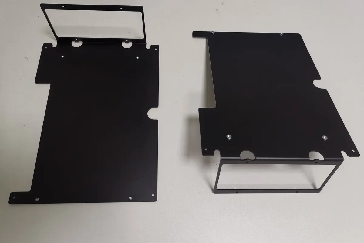
A UAV sensor bracket is easy to underestimate. It can look like a small plate, a bent-looking arm, or a compact housing with a handful of holes. In service, though, it is the mechanical reference between an airframe and a camera, thermal module, LiDAR unit, antenna assembly, or other payload. If its mounting faces move, its hole pattern is hard to assemble, or a cable edge is left sharp, the payload integration problem is pushed downstream.
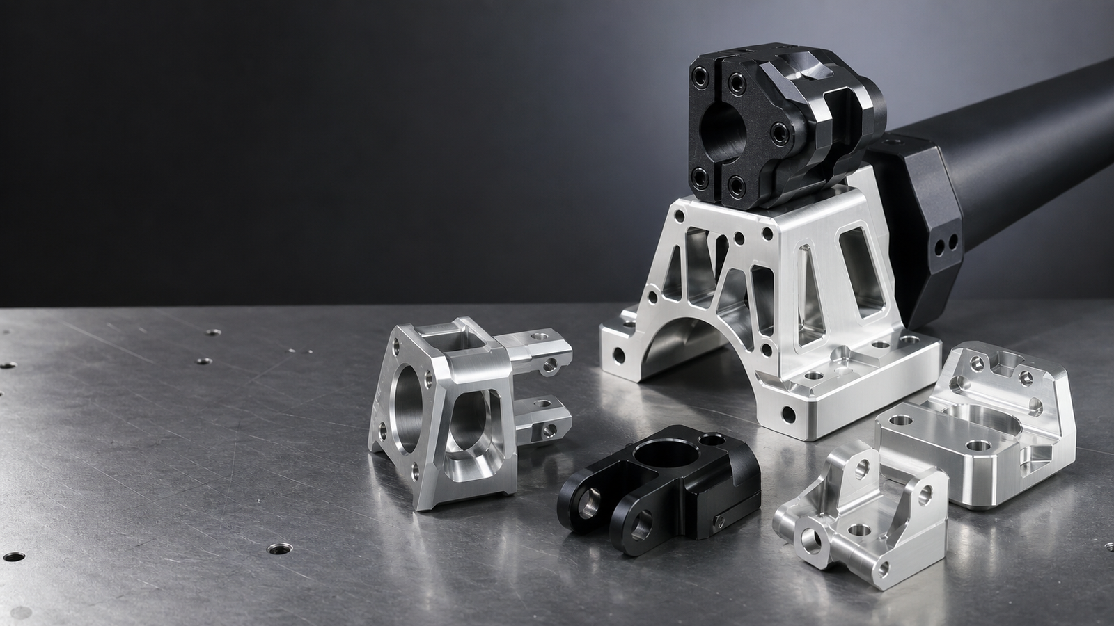
This is a representative manufacturing case note, not a customer story. The product photograph used for this article shows a real machined UAV mounting component from HDProto’s manufacturing image library. It is used as visual evidence of the type of work discussed here; it does not identify a customer, aircraft, qualification program, or measured in-flight result.
The manufacturing problem: one part, several interfaces
Sensor brackets and small payload housings generally have to satisfy several interfaces at once. One face meets the UAV structure. Another locates the sensor or its damping hardware. Holes may accept fasteners, dowels, threaded inserts, or cable clamps. Pockets reduce mass but cannot remove support needed around a boss, a fastener, or a thin-wall enclosure.
The useful question is not simply whether a shop can mill the outline. It is whether the part can be machined around the interfaces that matter most. For a sensor bracket, those are normally the airframe mounting datum, the payload-locating face, the hole pattern between them, and the protected cable path. Once these relationships are explicit, CNC programming and inspection can follow the part’s actual function.
Datum-first machining for payload alignment
For a representative aluminum bracket, a stable process begins by selecting a primary mounting face. That surface becomes the first machining and workholding reference. The payload face, locating features, and critical hole pattern are then finished in relation to it rather than as disconnected dimensions from the outside profile.
This matters because a bracket can meet individual size dimensions while still tilting a sensor relative to the airframe. The risk rises when a part has pockets on both sides, thin webs, or several setups. Removing material can release residual stress or reduce stiffness, which is why heavy roughing is usually completed before final finishing of the most important faces and bores.
A practical process plan often looks like this:
- Face and establish the primary structural datum.
- Rough pockets and external material while retaining support around critical interfaces.
- Machine the opposite side and non-critical relief features.
- Finish payload-locating faces, precision holes, and any close-fit bores from the defined datums.
- Deburr cable passages and edges before surface treatment.
The exact sequence changes with geometry and material, but the principle stays the same: do not finish a locating relationship before the cuts most likely to move it are complete.
Material selection is an interface decision
6061-T6 aluminum is a sensible starting point for many UAV sensor brackets and housings. It is relatively easy to machine, offers a useful strength-to-weight balance, and accepts anodizing well. 7075-T6 may be considered when a compact section needs more stiffness or strength, but the design still needs enough material around threads, tight internal corners, and mounting bosses. Neither alloy substitutes for a clear load path.
Engineering plastics can make sense for covers, insulating spacers, and non-structural enclosures. Stainless steel can be appropriate for pins, shafts, inserts, or local wear points. Using dense material for an entire payload mount, however, should be a deliberate system decision because mass at the payload affects the wider airframe and gimbal design.
The RFQ should specify the alloy and temper where relevant. “Aluminum” alone leaves too much room for unintended differences in machining behavior, finish appearance, and part performance.
Features that deserve attention on the drawing
Not every feature needs the same tolerance. Applying tight limits to every pocket wall increases cost without necessarily improving payload performance. Instead, separate motion- or alignment-critical features from ordinary clearance geometry.
| Feature | Why it matters | Useful drawing note |
|---|---|---|
| Airframe mounting face | Establishes the part reference | Identify as datum A where appropriate |
| Sensor mounting face | Controls payload orientation | Define flatness or parallelism only if function requires it |
| Locating holes or dowel bores | Makes assembly repeatable | Relate position to functional datums |
| Cable windows and slots | Protects wiring during vibration and service | Require edge break / deburr and clearance |
| Lightening pockets | Controls mass without losing stiffness | Keep material at bosses and interface transitions |
For a sensor housing, also show connector envelopes, screw head clearance, gasket lands if used, and any areas that cannot receive anodize buildup. A housing that closes on the bench but pinches a connector or rubs a cable in service has not solved the integration problem.
Finish and cable protection are part of the design
Anodizing is commonly specified for aluminum UAV hardware to improve corrosion resistance and provide a consistent appearance. Black anodizing may suit optical payload hardware where reduced visible reflection is helpful; clear anodizing is often chosen for a natural metallic appearance. The finish decision should be made before finalizing close-fitting holes, threads, grounding locations, or masking needs.
Sharp edges deserve equal attention. A cable slot that is technically within profile tolerance can still abrade insulation under vibration. A radius or intentional edge break, called out on the drawing and confirmed during deburring, is more reliable than expecting an assembler to correct every edge manually.
Inspection should prove relationships, not just isolated dimensions
The most meaningful inspection plan checks the relationships the assembly relies on: the distance and orientation between mounting faces, the position of the payload hole pattern relative to those faces, and the condition of cable-contact edges. A coordinate measuring machine can be useful for complex positional and geometric checks; calibrated gauges, height measurement, thread gauges, and visual inspection also have clear roles depending on the part.
The photo evidence here should not be read as a claim of a particular tolerance, certification, or flight test. Those requirements must come from the buyer’s drawing and project documentation. The purpose of early engineering review is to identify the inspection points that actually matter before the program is released.
What to include in an RFQ for a UAV sensor bracket or housing
Send a 3D model plus a 2D drawing that marks the assembly-critical features. Include the payload envelope or model when it can be shared, the airframe interface, material and finish, target quantity, and any thread, insert, masking, or marking needs. If a feature is tied to sensor aim, optical alignment, vibration isolation, or cable routing, say so. Functional context is often the fastest way to avoid an otherwise correct but awkward-to-assemble part.
For broader component planning, see our CNC machined drone components guide, gimbal bracket machining guide, and CNC UAV drone parts capability page. When the bracket needs to move from a functional sample into controlled repeat batches, review low-volume CNC machining.
Takeaway
The value of CNC machining a UAV sensor bracket or housing is controlled geometry at the interfaces: airframe, payload, fasteners, and cables. Start with datums, remove weight without undermining the load path, plan finish before fit features are frozen, and inspect the relationships that drive assembly. HDProto can review CAD, drawings, materials, finish requirements, and prototype or low-volume quantities for custom UAV machined parts.