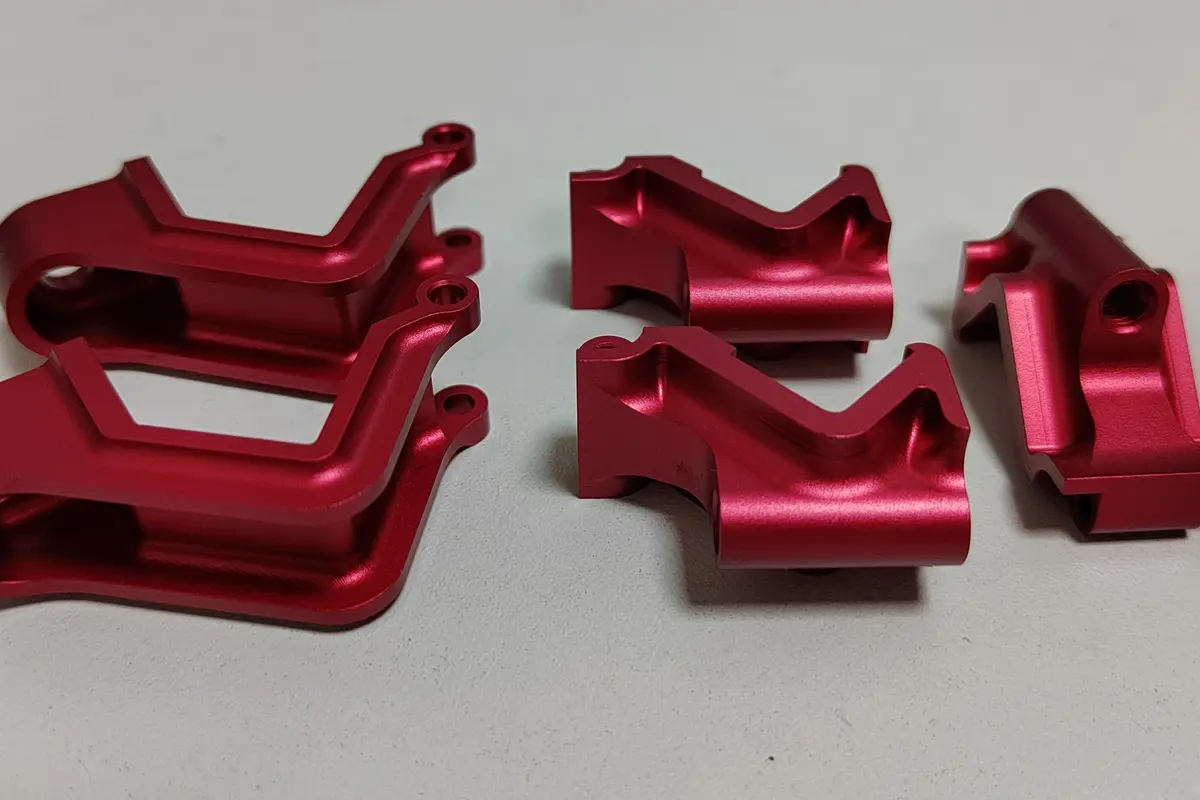
An anodized UAV gimbal mount has two jobs that work against each other: it must be light enough to respect the aircraft’s payload budget and stiff enough to hold a camera or sensor interface in a repeatable position. The part may be compact, but it is not a cosmetic accessory. Its faces, hole locations, wall transitions, and finish all influence how easily the payload can be installed and serviced.
This article is a representative manufacturing case note rather than a named customer case study. The cover photograph shows a real anodized CNC-machined UAV bracket from HDProto’s local image library. It demonstrates the general component type described below, but it does not establish a customer relationship, platform specification, flight-test outcome, certification, or universal tolerance claim.
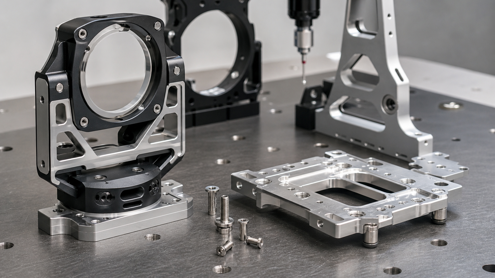
Start with the payload load path, not the outside shape
Gimbal mounts are often designed around a camera envelope and an existing bolt pattern. That is necessary, but it is not enough. The engineering review needs to identify how payload mass is transferred into the aircraft, where the mount is supported, and where a damping element or service interface sits. A thin pocket can be perfectly machinable and still create an avoidable flex point between two critical faces.
For a representative machined aluminum mount, the design is best understood as a chain of interfaces: airframe to mount, mount to damping or gimbal assembly, and gimbal assembly to payload. The faces and holes that locate these interfaces should be protected in both the machining plan and the inspection plan. Lightening pockets, cosmetic contours, and non-locating reliefs come after that hierarchy.
Why CNC machining fits prototype and low-volume gimbal hardware
CNC milling makes it possible to produce complex brackets without committing to dedicated tooling. That is useful where the payload, cable route, airframe, or mounting pattern is still evolving. A program can incorporate pockets, counterbores, threaded features, locating faces, and controlled internal radii directly from the CAD model.
For production, the same logic supports repeatable batches if the drawing makes functional features clear. That does not mean every dimension needs an extreme tolerance. It means the tolerances, datums, and inspection effort should be concentrated where the assembly needs them.
Typical CNC-machined gimbal-mount features include:
- milled side frames and adapter plates;
- flat payload interfaces and stepped mounting faces;
- clearance holes, threaded holes, and counterbores;
- lightening pockets with retained material around fasteners;
- cable passages with intentional edge treatment; and
- surfaces prepared for anodizing, bead blasting, or marking.
Aluminum choice: 6061-T6 versus 7075-T6
6061-T6 is widely used for UAV brackets because it gives a practical balance of machinability, cost, weight, and anodizing compatibility. It is suitable for many payload adapter plates, camera brackets, and general structural mounts. 7075-T6 can be a useful option when a smaller section needs greater strength or stiffness, but the tradeoffs should be reviewed in the actual geometry rather than assumed from an alloy name.
The right choice depends on load direction, support spacing, target weight, corrosion environment, finish, and cost. A heavier alloy cannot fix a weak geometry; a lighter geometry cannot be judged without understanding the mounting interfaces. Sending the payload mass, orientation, and basic use case with the RFQ enables a more useful manufacturing discussion.
Machining sequence: protect the faces that set orientation
An anodized bracket is often machined in two or more setups. Workholding has to be stable without damaging a finished face or leaving the final locating surfaces unsupported. A common approach is to establish a primary datum face, rough the heavy material removal first, then finish the locating faces and hole pattern after the part has reached its near-final stress state.
Deep pockets and thin walls make this especially important. Removing material changes how a part is supported and may reveal movement in the stock. For that reason, finishing a payload face early and then aggressively pocketing the opposite side is a risky sequence. The final process should instead preserve the relationship between the primary aircraft interface and the payload-locating interface.
Plan anodizing before final dimensions are released
Anodizing is not a last-minute color instruction. It affects close fits, threaded features, electrical contact areas, cosmetic expectations, and the order of operations. Black anodizing is common for camera and optical-payload hardware because it can reduce visible reflection; clear anodizing is often selected when a natural aluminum appearance is preferred. Both need clear specification.
Before machining, clarify:
- which surfaces are cosmetic and which are functional;
- whether threads, precision holes, or mating faces need masking or post-process control;
- whether bead blasting is required before anodizing;
- whether laser marking is needed and where it can be placed; and
- whether the finish must match another assembly component.
The photograph on this page is evidence of an anodized bracket form, not evidence that every finish or fit combination is appropriate. Finish thickness and masking requirements should always be tied to the part drawing.
Vibration and cable routing require physical clearance
A gimbal mount is part of the vibration path between propulsive hardware, airframe structure, isolators, and payload. Machining cannot choose the damping strategy, but it can accurately reproduce the geometry that strategy depends on. Flat support faces, correct hole locations, deburred cable windows, and clearance around connectors prevent common integration problems.
Cable routing deserves a visible place in the model. The route must account for the gimbal’s range of motion, bend radius, connectors, fastener heads, and edges that may see vibration. A simple slot can become a failure point if its edges are sharp or its placement forces repeated cable contact.
Inspection points for a payload-critical bracket
Inspection should be proportional to function. The key checks commonly include the positional relationship between the aircraft mounting pattern and the payload pattern, flatness or parallelism where the assembly requires it, thread condition, deburring, and finish appearance. Complex geometry may warrant CMM inspection; simpler checks can be completed with appropriate gauges and visual verification. What matters is that the method proves the datum relationships, not only the overall length and width.
Avoid treating representative part photography as inspection documentation. A production requirement needs an approved drawing, revision control, and an agreed inspection plan.
RFQ checklist
For a useful quote and DFM review, send STEP, IGES, or X_T data along with a PDF drawing. Identify material and temper, quantity, finish color, thread specifications, inserts, critical datums, target payload envelope, and any masked areas. Mark which faces locate the payload and which holes are simply clearance features. If the bracket must assemble with a purchased gimbal or a vibration isolator, include the relevant interface dimensions.
Related resources: gimbal bracket CNC machining, drone arm CNC mounts, and our CNC UAV drone parts capability page. For functional samples before the mount geometry is frozen, see rapid CNC prototyping services.
Takeaway
An anodized UAV gimbal mount should be managed as a payload interface, not merely an attractive milled part. A datum-led machining sequence, practical lightening geometry, pre-planned finish, protected cable edges, and inspection of the actual assembly relationships make the part easier to integrate. HDProto can review custom UAV gimbal brackets for prototype and low-volume CNC machining from your CAD and drawings.