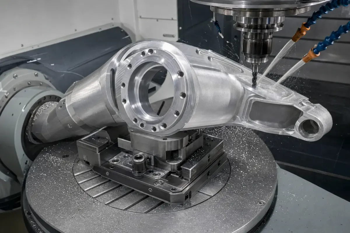
A robot joint interface housing is where motion hardware meets structure. Depending on the machine, it may locate a bearing, motor, reducer, cover, encoder, cable outlet, or adjacent arm section. Its outer shape can be highly distinctive, but the manufacturing priorities are straightforward: preserve the rotation and mounting datums, avoid distortion while removing material, and make the assembly repeatable.
This is a representative manufacturing case note, not a claim about a named robot program. The cover image is a real representative robot-machining image from HDProto’s local content assets. It illustrates the category of precision robot component discussed here; it is not proof of a particular end customer, performance result, certification, production quantity, or tolerance unless those are defined in project documentation.
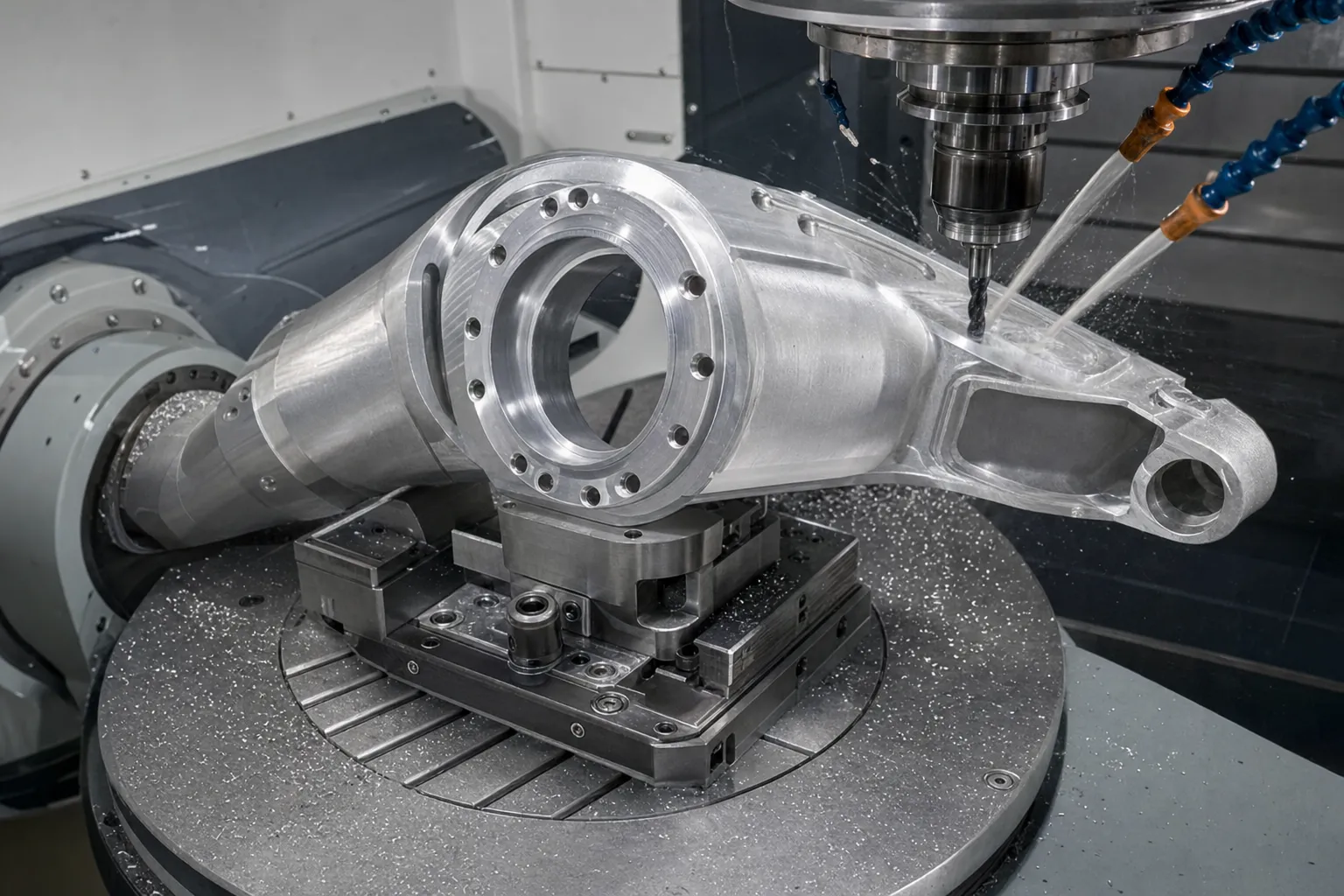
The real part is the relationship between the interfaces
A joint housing often combines a large bore or circular interface with a mounting face, fastener pattern, pockets, and cover features. A CNC program can make all of these elements, but their relationship is the point. A bore that is round but not correctly located from the motor face can complicate assembly. A cover face that is flat but tilted from the joint axis can create preload or sealing issues. A lightened housing can become less stable if ribs and bosses are removed without regard to the load path.
For a representative robot housing, begin by classifying features into three groups: motion-critical, assembly-critical, and non-critical. Bearing or reducer interfaces, dowel holes, and motor faces are usually motion- or assembly-critical. Cable windows, cosmetic pockets, and external profiles are often less sensitive. The grouping guides machining sequence, tolerances, and inspection effort.
Datum planning before CAM programming
Good robot housing machining begins with the datum scheme on the drawing. Select a stable primary face or interface, a secondary locating direction, and a tertiary feature where the design requires it. The bearing bore, mounting pattern, and mating faces can then be machined and measured from the same functional reference structure.
This approach prevents a frequent problem: features are individually measured from convenient edges rather than from the interfaces that the robot uses. For an assembly with a rotating axis, coaxiality, perpendicularity, bore position, and mounting-face orientation may be more meaningful than an impressive list of isolated plus/minus dimensions.
Rough first, then finish the precision interfaces
Robot housings are commonly pocketed to reduce mass and make room for motors, gears, wiring, or covers. Deep pockets and thin walls can change how the blank responds to clamping and cutting forces. If a critical bore is finished before the bulk of material removal, later cuts may affect its relationship to the mounting face.
A sound representative sequence is to establish a stable reference, rough major pockets while leaving support where needed, machine the opposite side, and finish the critical bore and interface faces after the heavy stock removal is complete. The specific setup depends on geometry, material, stock form, and quantity, but the purpose is consistent: protect the functional geometry until the part is stable.
Material and design choices for automation housings
6061-T6 aluminum is a practical option for many robot and automation housings. It is machinable, relatively light, and compatible with common anodized finishes. 7075-T6 can be considered where a high-strength, compact aluminum section is needed. Steel or stainless steel may be appropriate for selected high-load or wear interfaces, though weight, machining time, and corrosion protection should be considered as part of the complete assembly.
The right choice is driven by load path, environment, assembly method, finish, and price target. A material callout alone does not specify a reliable housing. Designers should also provide realistic wall thickness, internal radii that accommodate cutters, access for fastening tools, and clear treatment of threads, inserts, and bearing fits.
What should be tight and what can be practical
Over-tolerancing an entire housing costs money and can extend lead time without making the robot better. A practical drawing concentrates the strictest control on the interfaces that locate the rotational axis or repeat an assembly location.
| Feature | Manufacturing concern | Better specification approach |
|---|---|---|
| Bearing or reducer bore | Axis location and fit | Define fit and geometric relation to the functional datum |
| Dowel holes | Repeatable rebuild and alignment | Specify position from the mating-face datum |
| Motor/reducer face | Squareness and seating | Apply flatness or perpendicularity only where required |
| Weight-reduction pockets | Deflection and cycle time | Use practical radii and leave support around bosses |
| Cable openings | Cable protection and assembly access | Define clearance and deburr requirements |
The actual tolerance values should come from the assembly design. A representative content article should not replace a controlled drawing or a fit calculation.
Finish, threads, and assembly protection
Anodizing can improve corrosion resistance and provide a consistent appearance on aluminum housings. As with any machined assembly interface, decide in advance how finish affects bearing seats, threaded holes, electrical grounding points, and mating faces. If a precision feature must be masked or machined after finishing, state it in the production notes instead of relying on inference.
Threaded features also need complete specifications: size, standard, depth, through or blind condition, and insert requirements if applicable. Cable windows and service openings should have an intentional edge break or radius. These details are comparatively inexpensive in CAD and can save an assembler from correcting sharp edges during a build.
Inspection should match the joint’s function
Inspection for a robot joint housing should verify the datums and interfaces that determine assembly. A CMM is useful for complex positional and geometric relationships; bore gauges, pin gauges, height measurement, thread gauges, and visual inspection may be suitable for other features. The inspection plan should be agreed before production when the part contains critical motion features.
Photography provides helpful visual context but is not a substitute for an inspection report. The representative image here supports the existence of this component category in the manufacturing portfolio. It does not claim a measurement, qualification, or performance level for a future project.
RFQ inputs that improve a robot housing quote
Provide a native 3D model or neutral CAD file and a revision-controlled 2D drawing. Identify material, temper, quantity, finish, critical datums, bore or bearing requirements, thread details, inserts, and any purchased components that define interface geometry. It also helps to explain whether the part is a prototype, a pilot build, or repeat production, and which dimensions are essential to the joint’s function.
For related CNC guidance, see robot joint housing machining lessons, industrial robot parts DFM checklist, and the industrial robot parts CNC machining page. For controlled bridge builds and repeat releases, see low-volume CNC machining.
Takeaway
Robot joint interface housing machining is fundamentally about controlled relationships: the axis, mounting faces, locating features, and protected cable or service interfaces. A clear datum structure, rough-before-finish strategy, sensible tolerance allocation, and functional inspection plan turn a complex-looking part into a manufacturable one. HDProto can review custom robot housing CAD and drawings for prototype and low-volume CNC machining.